Concept illustration
Read diagram notes
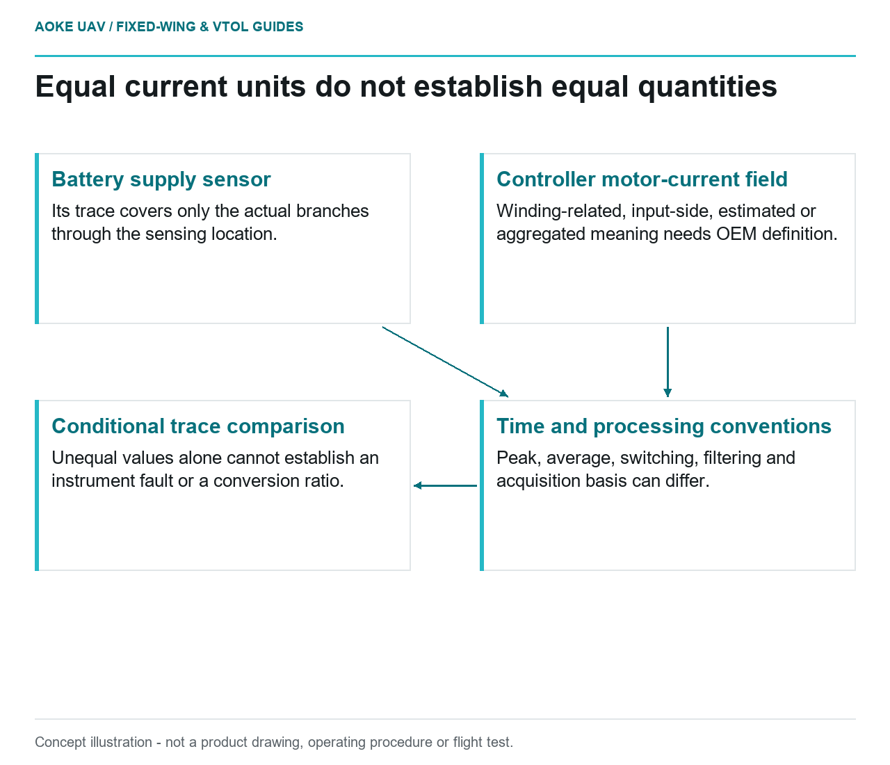
- Battery supply sensor: Its trace covers only the actual branches through the sensing location.
- Controller motor-current field: Winding-related, input-side, estimated or aggregated meaning needs OEM definition.
- Time and processing conventions: Peak, average, switching, filtering and acquisition basis can differ.
- Conditional trace comparison: Unequal values alone cannot establish an instrument fault or a conversion ratio.
Name the path before comparing the numbers
In a hypothetical large civil fixed-wing VTOL project, a flight-log review places a battery-monitor current trace beside a controller field named motor current. The traces differ, and the team wants to know whether either instrument is wrong. The first task is to define the measurements. This example is an original review scenario, not a diagnosis of a real propulsion system.
The maxon reference defines motor current within its electromechanical model, linking it to torque through the torque constant and using winding current in its loss discussion. ArduPilot’s Common Power Module documentation instead describes an analog module measuring battery voltage and current consumption in the battery supply path. These sources describe different contexts, not an interchangeable current definition. [1] [2]
For the proposed review, label the physical sensing location on an electrical diagram. Identify whether each field concerns a battery lead, a particular controller input, a winding-related quantity or an aggregation whose definition is not yet known. A matching unit does not resolve an unidentified measurement boundary.
Ask what the controller actually reports
The available maxon reference is a generic motor explanation, not the documentation for the controller in this hypothetical aircraft. It does not establish how that controller defines or transmits phase-current telemetry. Consequently, this article gives no formula converting battery current into a motor-side current, and no claimed ratio between the two.
Request the exact controller manufacturer’s definition of the field, including whether it is measured or estimated and what peak, average or other convention applies. Ask how switching and filtering are represented in that reported value. These are evidence questions to the OEM, not claims that a particular implementation behaves in a specified way.
For the large fixed-wing installation, also identify which loads are included at each sensing location. If the schematic places payload or avionics branches outside one monitor’s path, ask for that branch accounting before calling its trace total aircraft current. Do not assume the battery monitor and controller observe the same collection of loads.
Treat scaling and timing as part of the comparison
ArduPilot documents separate conversions for analog battery-voltage and current inputs, along with a current offset. The page also describes comparing reported values with independently collected meter readings for a supported secondary-monitor arrangement. This provides concrete evidence that displayed current depends on configuration and calibration, not just a field name. The page concerns specific analog-monitor arrangements. [2]
In the hypothetical comparison, preserve the sensor identity, scaling configuration, offset and relevant firmware record. Ask each supplier for the acquisition and reporting time basis before comparing transient shapes. A slowly reported field should not be described as a switching-waveform measurement without applicable evidence. No sampling rate or measurement accuracy is established here.
Keep original records alongside any aligned plots. If the team resamples, filters or shifts a trace during review, document that processing rather than presenting the result as untouched telemetry. This proposed recordkeeping method is especially useful when the disputed event occurs during the aircraft’s transition rather than during a steady cruise interval.
Separate a measurement question from a rating decision
Maxon’s motor model uses current to discuss torque and winding heating. That does not make a motor-model quantity a battery-lead capability, or make a controller field a verified continuous rating. The applicable component documentation must identify the quantity and conditions being rated before the project applies it. [1]
For this civil fixed-wing project, a useful conclusion would list which fields are defined, which sensing paths are calibrated and which timing questions remain open. If the controller OEM definition is still absent, the comparison remains incomplete even when the plot looks plausible. Do not hide that gap behind an assumed conversion.
The immediate deliverable is therefore a traceable measurement map, not a fault verdict, controller setting or cable recommendation. Once the quantities and their boundaries are established, the team can decide which further evidence is needed. Until then, unequal current numbers alone do not establish an instrument fault or demonstrate that the installed propulsion system meets its requirements.