Concept illustration
Read diagram notes
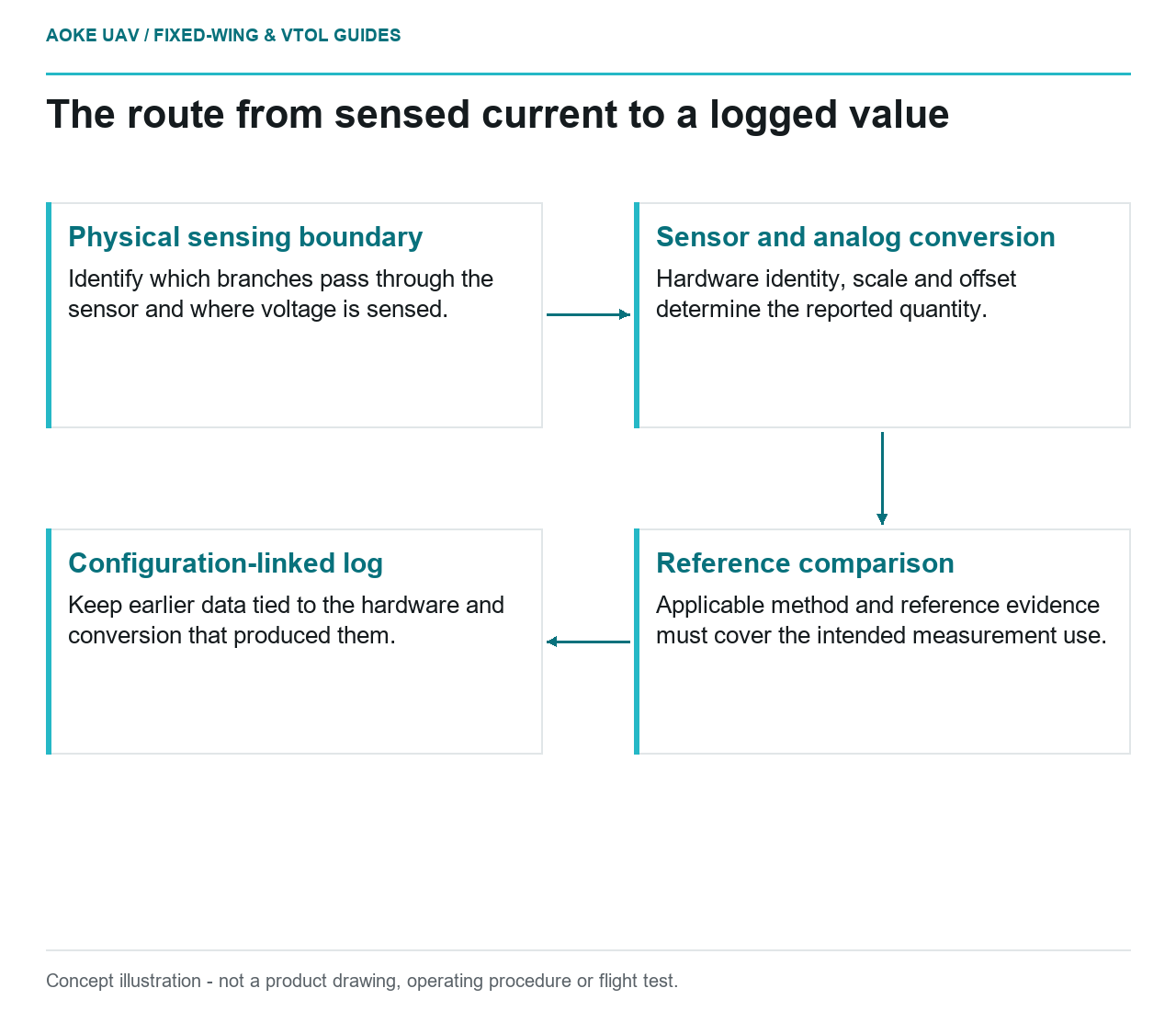
- Physical sensing boundary: Identify which branches pass through the sensor and where voltage is sensed.
- Sensor and analog conversion: Hardware identity, scale and offset determine the reported quantity.
- Reference comparison: Applicable method and reference evidence must cover the intended measurement use.
- Configuration-linked log: Keep earlier data tied to the hardware and conversion that produced them.
Identify what the dashboard is displaying
A hypothetical large fixed-wing aircraft has completed a civil mapping evaluation, and the team wants to use its power log in a mission-energy discussion. Before interpreting the dashboard, the reviewer discovers that the installed monitor’s scaling record is missing. The immediate question is measurement traceability, not whether the aircraft achieved a promised endurance.
ArduPilot’s Common Power Module page describes analog modules that both provide an autopilot supply and support measurement of battery voltage and current consumption. It also distinguishes typical module limits from the need to confirm specifications directly with the vendor. The document is a specific monitor example, not a suitable module recommendation for the large aircraft imagined here. [1]
Ask which sensor, hardware revision and input configuration produced each field. Preserve the raw record if available and identify where a reported value has already been scaled. A labeled graph is useful communication, but the label alone does not establish the instrument’s range, conversion or installation.
Trace the sensing point and electrical branches
The documented common-module arrangement places the battery on one side of the module and the ESC or distribution board on the other. That description helps identify the intended measurement path within the example. It does not establish where a monitor sits in another aircraft or which branches that monitor includes. [1]
For the illustrative fixed-wing project, draw the actual sensing point and the propulsion, avionics and payload branches around it. Ask which loads pass through the current sensor and where the voltage is sensed. If a payload supply bypasses that sensor in the proposed schematic, do not label its reading whole-aircraft current without further accounting.
For a fixed-wing VTOL derivative, make the same map for any separate lift and forward-propulsion supplies. This is an original documentation prompt, not a claim that separate supplies are required. The aim is to avoid comparing channels with different measurement boundaries as if they described the same electrical path.
Review conversion, offset and reference evidence
ArduPilot documents distinct voltage and current conversion parameters for analog inputs and a current-offset parameter. Its secondary-monitor example instructs comparison of reported voltage and current with meter measurements when setting the relevant conversion factors. That supports asking for reference evidence, while leaving the exact installed sensor’s procedure and limitations with its applicable documentation. [1]
For this project, request the approved calibration method, reference instrument identity, reference status, observed values and configuration used. Ask whether the evidence addresses both the conversion and any relevant offset, rather than assuming a single matching reading resolves the entire useful range. This article does not establish accuracy tolerances or a replacement calibration procedure.
Keep environmental and loading conditions attached to the observations. Ask for the sensor’s applicable measurement range and behavior outside it before interpreting unusually flat traces. Do not infer that a logged value is trustworthy simply because the display software accepted it. Nor should a disagreement be assigned to the battery before the measurement chain has been checked.
Retain change history before using the log as evidence
A proposed monitor record should connect sensor identity, wiring boundary, configuration export, calibration evidence and log timestamps. If hardware, firmware or scaling changes, retain the earlier record and state which logs used which configuration. This is a suggested review method, not a universal calibration standard.
The common-module document also warns that example modules have supply and continuous-current limitations and directs readers to manufacturer ratings. Calibration of a measurement channel must not be mistaken for confirmation that the module’s power path is suitable for an industrial fixed-wing installation. Those are separate evidence questions. [1]
The outcome of the hypothetical mapping review may be a qualified log suitable for a narrowly defined comparison, or an unresolved measurement record requiring further work. Either is more honest than treating an unverified dashboard as an energy audit. No mission reserve, battery health verdict or endurance guarantee follows from this generic monitor documentation alone.
Related reading
- Motor Current and Battery Current Are Not the Same Measurement
- Reporting UAV Survey Uncertainty Without False Precision