Concept illustration
Read diagram notes
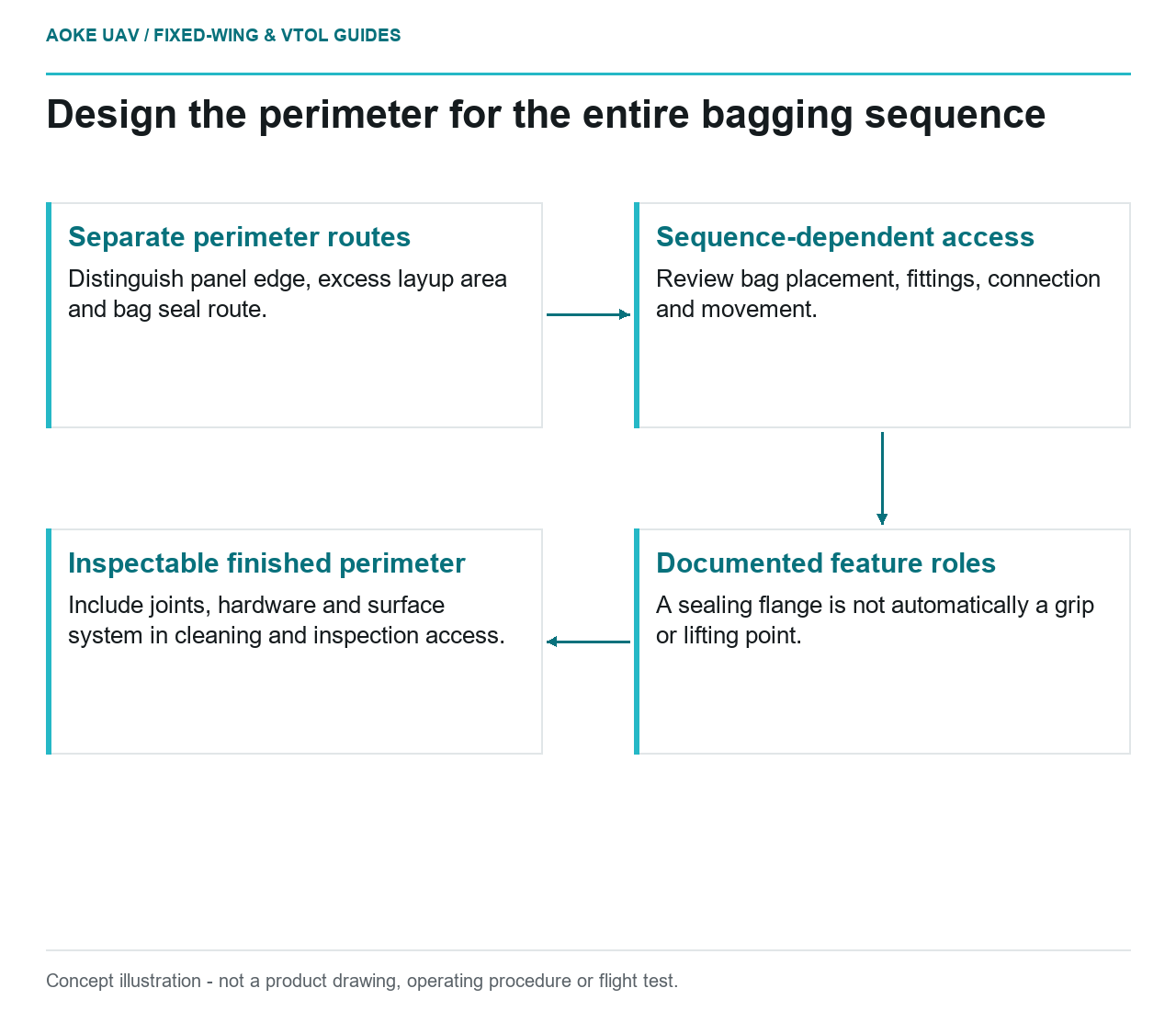
- Separate perimeter routes: Distinguish panel edge, excess layup area and bag seal route.
- Sequence-dependent access: Review bag placement, fittings, connection and movement.
- Documented feature roles: A sealing flange is not automatically a grip or lifting point.
- Inspectable finished perimeter: Include joints, hardware and surface system in cleaning and inspection access.
A hypothetical wing-skin layup tool has an accurate central surface but an awkward perimeter. The civil-aircraft team needs to know whether technicians can bag, connect, handle, inspect and clean it without defeating its intended geometry. For a multi-meter tool supporting a large fixed-wing project, that is a design question rather than a last-minute shop adjustment. This scenario describes no GAUTEN hardware and supplies no universal flange dimensions.
Bag seal path around the perimeter
Begin with a perimeter map that distinguishes the finished panel boundary, excess layup area and intended bag seal route. In this proposed fixed-wing workflow, each route should be identifiable on the drawing and physically accessible. Do not assume the aerodynamic surface model contains enough information to define the manufacturing perimeter.
The Stratasys guide extends tool surfaces beyond the part edge in its layup-tool examples and separately addresses surface versus envelope bagging. It also discusses edge rounding to avoid piercing bagging material. Those concepts support reviewing the full tool outline, not selecting an arbitrary flange width from an illustration. [1]
Walk the proposed seal route through corners and segment joints. Ask whether a technician can prepare and inspect it without reaching over an unprotected layup area. These are hypothetical access questions; the selected bagging materials and approved process must determine what surface condition and space are actually required.
Clearance for fittings and handling
For the large fixed-wing tool, propose a physical sequence review rather than a clearance check in only one assembled view. Consider the order of material placement, bag placement, fitting access, connection, movement and removal. An area available before layup may not be available later in the intended process.
Stratasys describes stabilizing features and separate cradles as options in its tool-design examples. It also discusses flanges that assist demolding in a deep female tool. These illustrate different functions around a mold, not permission to use a thin printed flange as a lifting point. [1]
Assign each perimeter feature one or more documented roles. A surface meant for sealing should not silently become a gripping surface, and a fitting location should not be assumed suitable for handling loads. The project needs its own engineering definition of support and handling arrangements, including what must remain accessible at each stage.
Local reinforcement at hardware
The OEM guide discusses localized reinforcement around inserts and bushings and describes metal hardware incorporated into FDM tools. This makes local construction a relevant design topic where fittings or other hardware are proposed. It does not establish a flange thickness, insert retention value or allowable hose load for this mold. [1]
In the hypothetical review, identify each proposed hardware interface and request evidence for its installation, function and inspection. Show which part of the printed construction supports it, how its position will be checked and whether replacement changes the surface or seal route. Do not hide these details behind a generic instruction to add more infill.
Check the complete process environment, too. Stratasys ties tool design to temperature, pressure, bagging arrangement and intended life. The proposed interface assessment should therefore cover the actual process configuration rather than treating room-temperature hand assembly as sufficient. This article intentionally provides no installation settings or cure-tool strength calculation. [1]
Inspection and cleaning access
Treat flange geometry as controlled tooling geometry, not disposable excess. For this fixed-wing project, specify which regions require dimensional checks, surface-condition checks or both. Include the joined and finished configuration. If a joint, fitting or support blocks the inspection method, resolve the conflict in the design rather than marking the region inaccessible after manufacture.
The guide states that sealers should be chosen for compatibility with the printed material, expected exposure and tool life. That makes the final surface system part of the access review: proposed cleaning and inspection must preserve the system described by the actual supplier instructions. No universal solvent or cleaning procedure follows from this article. [1]
The useful handoff is a perimeter workflow with named functions, clear access and inspectable interfaces. Have the responsible team review it before a full-scale print. An accurate central mold surface cannot compensate for a bagging flange that cannot be prepared, checked or used in the agreed manufacturing sequence.