A segmented printed wing mold is proposed for vacuum bagging in a hypothetical large fixed-wing civil-aircraft workshop. Its surface looks continuous, but the team still needs evidence that the intended vacuum boundary works in the selected process. This article frames that review; it is not an GAUTEN leak-test result, sealing recipe or approval of a laminate. The actual tool, materials and manufacturing instructions must define the acceptance method.
Printed porosity and leak paths
Stratasys explains that FDM bead construction leaves some internal porosity and that post-processing is typically needed for surface finish and vacuum integrity. Its guidance concerns particular FDM tooling materials and constructions. A visually smooth printed surface is therefore not, by itself, evidence of the vacuum performance described in that guidance. [1]
For this fixed-wing mold, first draw the intended vacuum boundary. Identify whether the process seals a bag to the tool or encloses the tool, and show how ports, joints and edge transitions participate. The review cannot meaningfully discuss a leak path without agreeing which surfaces are supposed to form the boundary.
Keep potential leakage locations as hypotheses until inspected or tested. The proposed checklist might include surface discontinuities, segment interfaces, fittings and the bag seal itself. That list organizes investigation; it does not establish that the printed material is the cause of any observed loss.
Sealing material process compatibility
The OEM guide says the sealing method depends on the application. It calls for compatibility with the printed material, appropriate cure-temperature exposure and anticipated tool life. It describes epoxy systems and adhesive-backed films as different approaches with distinct limitations rather than interchangeable surface treatments. [1]
NASA JSC PRC-6002 treats vacuum sealants, bagging and mold releases as ancillary consumables that must remain chemically inert toward part materials throughout processing. The document belongs to its defined sandwich-assembly context; it is not automatically a requirement for this UAV. It does, however, illustrate a compatibility question that the chosen process must resolve. [4]
In the hypothetical review, request the complete surface-stack identification and supplier instructions. A base polymer’s thermal property does not identify the sealer, its adhesion or the behavior of an assembled joint. Missing compatibility evidence is a reason to hold the proposal, not to assume that any familiar coating will do.
Joints and surface preparation
Stratasys discusses segmented tools joined through secondary operations and requires joining materials appropriate to the cure conditions. Its post-processing discussion addresses both surface quality and vacuum integrity. For a joined wing mold, those topics need to be reviewed together rather than approved in separate documents that never describe the final assembly. [1]
The fixed-wing team should identify the joint configuration, preparation route, local finishing and sealing sequence on the tool record. Ask what can be inspected before a coating hides the interface and what can be verified afterwards. Do not treat a uniform color or polished reflection as proof that the underlying boundary is continuous.
The guide specifically notes bagging limitations for adhesive-backed films: in its described approach, such films require envelope bagging unless combined with another sealing method. This prevents substituting a film into a surface-bagged concept without reassessing the boundary. The selected supplier documentation and actual tool evidence still govern the project’s decision. [1]
Leak checks tied to the tooling process
Define the proposed check in terms of its configuration and purpose: which assembled tool, fittings, bag arrangement and process state it evaluates. The responsible manufacturing engineer must set the method, observation period and acceptance limits from applicable process requirements. No universal vacuum level or allowable loss is supplied here.
For the hypothetical handoff, preserve results with the tool identity, surface-system revision and observations used to locate any discrepancy. State whether the evidence covers only a preliminary cold setup or the relevant processing conditions. Recheck after repairs or configuration changes according to the approved tooling plan rather than automatically carrying the earlier result forward.
Finally, separate vacuum-boundary acceptance from laminate acceptance. A satisfactory tool check addresses a manufacturing input, not the panel’s internal quality, wing strength or release of the fixed-wing aircraft. The review is complete only when its claim is narrow enough to match what was actually checked.
Related reading
Sources
- [1] FDM for Composite Tooling: Design Guide 2.0
- [4] Process Specification for the Assembly of Composite Sandwich Structures
Visual summary
Concept illustration
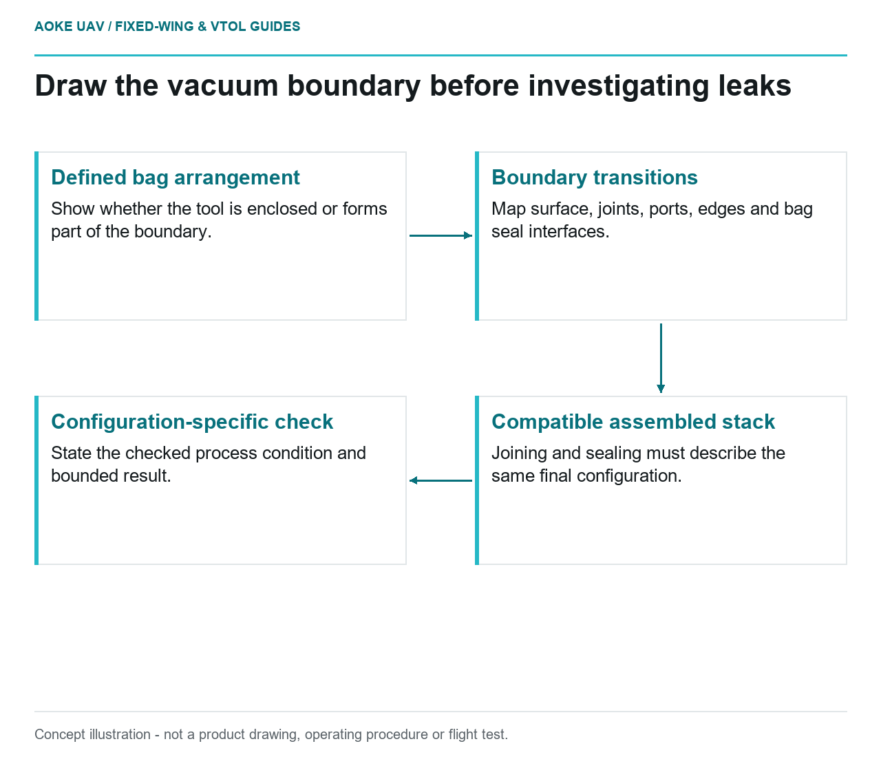
Read diagram notes
- Defined bag arrangement: Show whether the tool is enclosed or forms part of the boundary.
- Boundary transitions: Map surface, joints, ports, edges and bag seal interfaces.
- Compatible assembled stack: Joining and sealing must describe the same final configuration.
- Configuration-specific check: State the checked process condition and bounded result.