Concept illustration
Read diagram notes
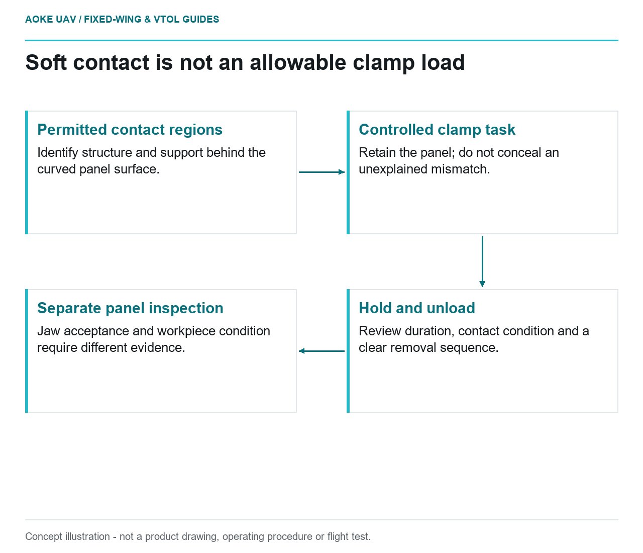
- Permitted contact regions: Identify structure and support behind the curved panel surface.
- Controlled clamp task: Retain the panel; do not conceal an unexplained mismatch.
- Hold and unload: Review duration, contact condition and a clear removal sequence.
- Separate panel inspection: Jaw acceptance and workpiece condition require different evidence.
Soft describes a contact material, not an accepted load on a composite part. Imagine a thin sandwich access panel being positioned during assembly of a large civil fixed-wing inspection aircraft. A custom printed jaw is proposed to follow its curved surface. This hypothetical review asks whether the jaw can locate the panel without demanding that an unsupported skin carry an undefined clamping load. It is not an GAUTEN process demonstration.
Begin with approved contact regions
Formlabs lists compliant printed interfaces among manufacturing-aid applications and emphasizes functional checking with the workpiece seated on its supports. That is a tool-design starting point, not a sandwich-panel handling limit. [2]
For the proposed fixed-wing panel, ask the responsible design authority to identify permissible support and handling regions. Lay those regions over the jaw contact model. A wide contoured pad is not our proposed substitute for knowing what lies behind the surface. Review the edge, core transitions, inserts and any local reinforcement as distinct features rather than calling the whole panel uniform.
Make support access visible in the assembly sequence. If a backing support must be removed to fit another component, reassess the clamping condition at that step. The jaw design should not rely on a hidden support that is present only in a drawing screenshot, nor on an operator holding the panel in the correct attitude by feel.
Treat clamp input as controlled
In this scenario, define what the clamp is supposed to accomplish: retention during a specified task, not correction of a distorted component. Agree how the intended clamp input will be established and recorded using application-specific evidence. No universal force or torque follows from the phrase printed soft jaw.
We would compare the unrestrained panel fit with the fit after location and clamping. If the apparent alignment becomes acceptable only after the clamp pulls the panel into shape, flag that as a finding. The team must distinguish intended assembly restraint from an unexplained dimensional discrepancy. Passing the part outline while restrained should not close that issue.
Formlabs warns about sustained loading of SLA tools and recommends relieving clamp forces after secondary operations. Its warning is specific tooling context, not a quantified lifetime prediction for every printing process. [2] Our proposed trial would therefore document both clamp duration and unloading, rather than reducing the test to a quick squeeze followed by a photograph.
Control surface contact and cleanliness
Identify everything between the jaw body and the panel: printed contact material, liners, coverings and any maintenance treatment. Obtain compatibility and cleanliness evidence appropriate to the next assembly operation. A jaw that seems acceptable for temporary handling may require a separate review if it touches an area later used for structural bonding or surface finishing.
Before the trial, define how the jaw will be cleaned and inspected without silently changing its working shape. Include the support-facing side, where a misplaced fragment would otherwise be difficult to notice during loading. Treat replacement liners or resurfacing as controlled changes where they affect the contact geometry.
For the large fixed-wing assembly, also check the operator’s access to release the part. An apparently protective interface is not useful if removal requires levering against the panel edge. Demonstrate a clear unloading sequence with a representative nonflight article and the intended surrounding fixture components installed.
Inspect the jaw and the workpiece separately
Our suggested acceptance record has two halves. One records jaw geometry, support seating and clamp behavior; the other records the panel condition before and after the task using a suitable inspection method. Visible marks are findings to investigate, but absence of obvious marks is not offered here as proof of undamaged sandwich structure.
Set review triggers for changed seating, damaged contact material or altered clamp behavior. Retain the relationship between the jaw revision and the panel drawing. The decision is whether this particular ground assembly aid deserves further controlled use, not whether a compliant print grants permission to clamp any composite airframe surface or proves a finished fixed-wing aircraft safe to operate.