Concept illustration
Read diagram notes
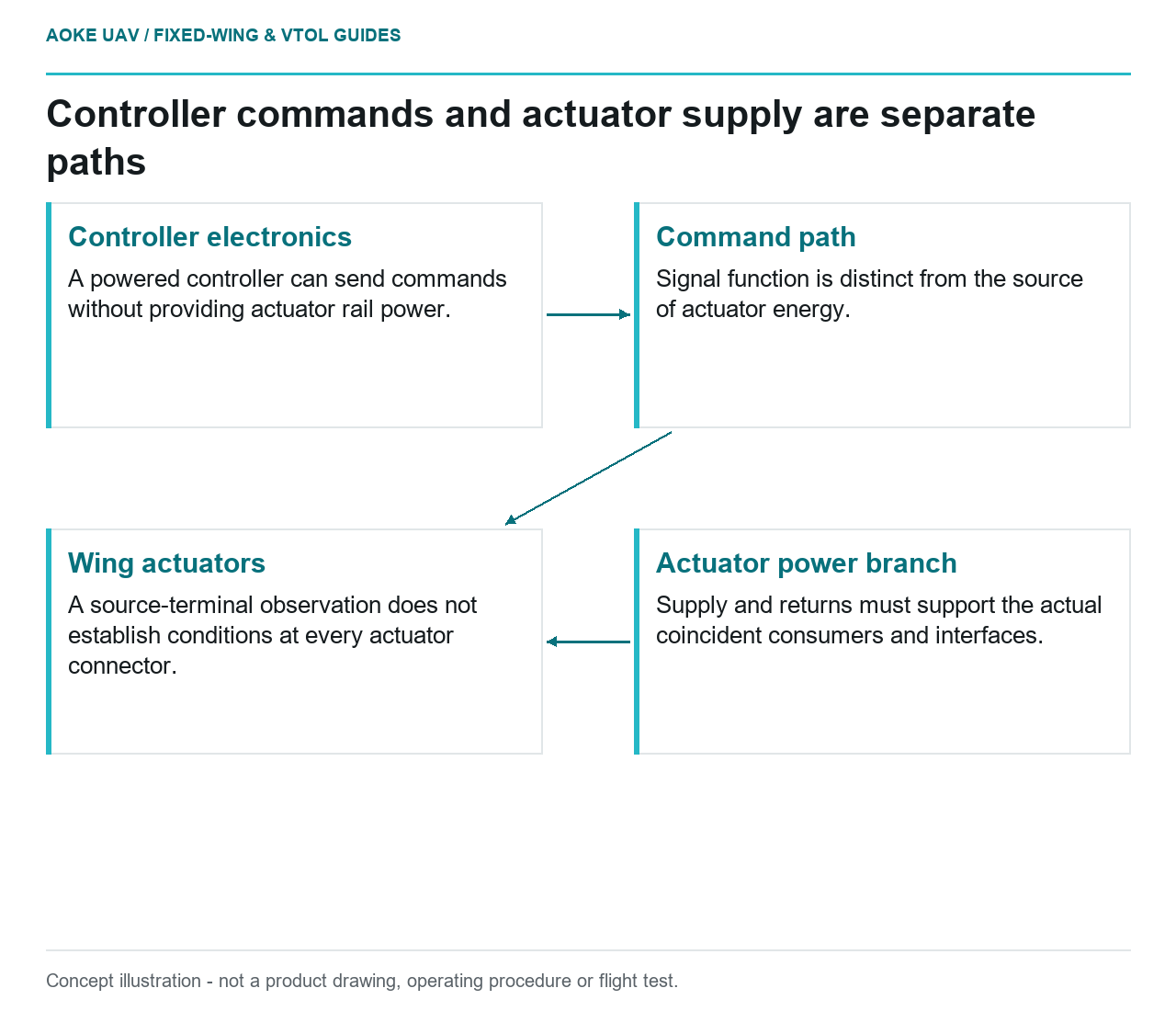
- Controller electronics: A powered controller can send commands without providing actuator rail power.
- Command path: Signal function is distinct from the source of actuator energy.
- Actuator power branch: Supply and returns must support the actual coincident consumers and interfaces.
- Wing actuators: A source-terminal observation does not establish conditions at every actuator connector.
In a hypothetical large fixed-wing survey aircraft, distributed wing actuators connect to an autopilot that powers up normally on the bench. The team has not documented the source feeding those actuators. A working controller is therefore answering the wrong acceptance question. This article concerns the actuator electrical supply: where power comes from, which combinations of loads are represented and what the complete installation evidence covers. It does not select a servo from wing area.
Controller supply versus servo rail
Draw the command path and the actuator power path separately for the example aircraft. Identify what the controller sends, where the actuator receives supply power and which return paths the applicable diagrams define. This prevents a signal connector from being treated as proof that its power contacts are energized, or a controller supply connection from silently becoming the supply for every wing actuator.
ArduPilot’s Powering the Pixhawk documentation states that the example Pixhawk does not supply the servo rail. It also discusses disturbances associated with servos in that architecture.[1] Those statements establish the importance of the distinction for the documented hardware. They do not establish the wiring, voltage range or protective components needed by another controller, a distributed actuator network or a large industrial fixed-wing installation.
Actuator voltage and current demands
Request the exact actuator and controller documentation, together with the proposed supply hardware. The evidence should distinguish allowable supply conditions from performance labels and identify which actuator states were included in any current report. If the supplier offers a single number without its conditions, retain the question as open rather than inventing an allowance. An actuator torque label is not the missing electrical supply specification.
For the hypothetical fixed-wing wing, organize consumers by the actual electrical branches, not merely by left and right mechanical location. Ask which accessories share each branch and whether the supplied evidence covers their combination. This creates a checkable inventory for the responsible electrical designer without claiming that a generic regulator or the autopilot’s input module is suitable for the resulting demand.
Simultaneous loading and wiring interfaces
The integration question includes coincident demands. Request evidence for the combinations the aircraft design identifies as relevant, including the basis for those combinations. Do not add an arbitrary multiplier to isolated servo figures and call the result a validated design. The review should also identify the wiring and connector configuration covered by the evidence, especially across detachable sections of a large wing.
The Pixhawk reference warns that servo activity can disturb a shared supply arrangement in its documented example.[1] That is not a universal prediction of a particular aircraft’s response. For this scenario, ask what measurements or analyses substantiate the chosen separation, regulation and interconnections. Record where a voltage observation was taken so a source-terminal trace is not mistaken for evidence at every actuator connector.
Aircraft-specific control-system evidence
Keep this review connected to, but distinct from, mechanical control-system acceptance. The aircraft load analysis and linkage arrangement determine what actuator behavior needs substantiation; the power review asks whether the electrical installation supports the specified behavior under applicable conditions. Neither discipline should fill the other’s missing data with a hobby rule. The resulting record should connect each electrical claim to the actuator and aircraft configuration it concerns.
A practical handoff is a controlled actuator-power drawing with an associated evidence matrix and unresolved-item owners. The matrix should make any omitted branch, undocumented shared consumer or unidentified supply component visible. No current rating, universal wire choice or flight procedure is supplied here. For the large fixed-wing example, the defensible result is a traceable electrical argument, not the inference that an illuminated autopilot proves powered and adequately supplied control surfaces.