Concept illustration
Read diagram notes
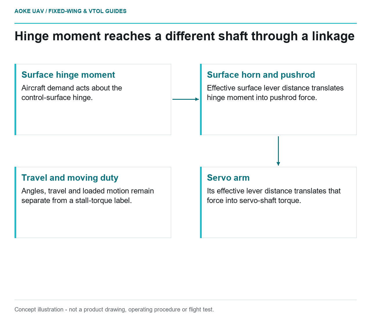
- Surface hinge moment: Aircraft demand acts about the control-surface hinge.
- Surface horn and pushrod: Effective surface lever distance translates hinge moment into pushrod force.
- Servo arm: Its effective lever distance translates that force into servo-shaft torque.
- Travel and moving duty: Angles, travel and loaded motion remain separate from a stall-torque label.
A hypothetical multi-meter fixed-wing survey aircraft needs a wing control actuator. Two supplier sheets show attractive torque labels, but the required surface motion and hinge moment have not been translated through the linkage. Comparing the labels directly with a wing-load number would skip that translation. The worked reasoning below is qualitative and explicitly illustrative: it selects no GAUTEN hardware, supplies no aircraft loads and creates no universal sizing margin.
Aircraft hinge load requirements
The aircraft input is a hinge moment: the turning demand about the control-surface hinge for a defined aircraft condition and surface position. The actuator output is torque about a different shaft. Those quantities need not be equal. They are connected by the actual control horn, pushrod and servo arm, not by wing area alone.
Pololu’s mechanics explanation defines torque through force and perpendicular lever distance and explains that a longer output lever gives less force for the same shaft torque.[1] Its servo introduction describes the output arm pushing or pulling linkages and treats torque and speed as separate specifications.[2] These primary explanations support the mechanism comparison, not actuator qualification for a large industrial fixed-wing aircraft.
For this original thought experiment, assume a rigid pushrod, freely moving joints and negligible friction. Start with an aircraft-defined hinge moment, without assigning it a value. The surface horn must turn pushrod force into that hinge moment. The servo arm must then produce that same ideal pushrod force at its own effective lever distance. Equal pushrod force does not imply equal torque at the two shafts.
Linkage geometry and structural interfaces
Compare two illustrative servo-arm positions on the same otherwise unchanged linkage. With a longer effective servo arm, the same pushrod force demands more servo-shaft torque. For the same small servo rotation, it also produces more pushrod motion. Moving the connection inward reverses that local tradeoff: less shaft torque for the same force, but less pushrod motion. This follows from the lever relationship, not a recommended horn setting.[1]
A longer effective surface horn can instead supply the required hinge moment with less pushrod force, while needing more pushrod travel for the same small surface rotation. The two sides must therefore be considered together. An arrangement that looks favorable for force may fail to supply required travel; a long servo arm that supplies travel may increase torque demand. Neither choice can be assessed from a stall label alone.
These comparisons use effective perpendicular distances to the pushrod’s line of action, not merely hole-to-pivot lengths. As the linkage moves, its angles change, so a favorable neutral-position comparison is not the complete travel assessment. Real joints, bracket flexibility and friction were excluded from the thought experiment. The aircraft’s actual linkage assessment must address them and the attachment reactions; this simplified reasoning is not a hardpoint strength calculation.
Supply voltage and duty conditions
Stall capability is also different from moving capability. Maxon’s generic motor diagrams place stall at zero speed, relate loaded speed to torque at a stated voltage, and distinguish continuous operating range from temporary overload. Its thermal discussion links allowable sustained current to heat dissipation.[3] These are bounded motor principles: a geared, controlled servo needs its own output-performance and duty documentation, not an aircraft rating inferred from the maxon chart.
In the hypothetical comparison, sheet A supplies only a stall label. It cannot demonstrate the required loaded movement time or repeated holding duty. Sheet B supplies an identified moving-output performance envelope and applicable duty conditions. B would permit a meaningful comparison only where the aircraft’s transformed torque, movement and duration requirements fall within the documented conditions. This is an evidence comparison, not a claim that a real candidate has passed.
Evidence for the complete control installation
For the large fixed-wing example, the decision is to withhold selection on sheet A alone, not automatically choose B. First establish the aircraft load basis; then map it through the controlled linkage throughout required travel; finally compare the resulting output demand with the actual actuator’s available performance and duty evidence. Supply conditions belong in that comparison, but electrical distribution design is a separate assessment.
No amount of torque-label headroom repairs missing travel, an undefined hinge-load case or unsupported repeated operation. Conversely, a smaller label is not proof of inadequacy without the same comparison. The useful outcome is a physically coherent requirement at the actuator shaft, with the actual installation still requiring substantiation rather than approval by a single catalog number.
Related reading
- Control Hinge Hardpoints in Composite Wings
- Printed Alignment Fixtures for Detachable Wing Assemblies