Concept illustration
Read diagram notes
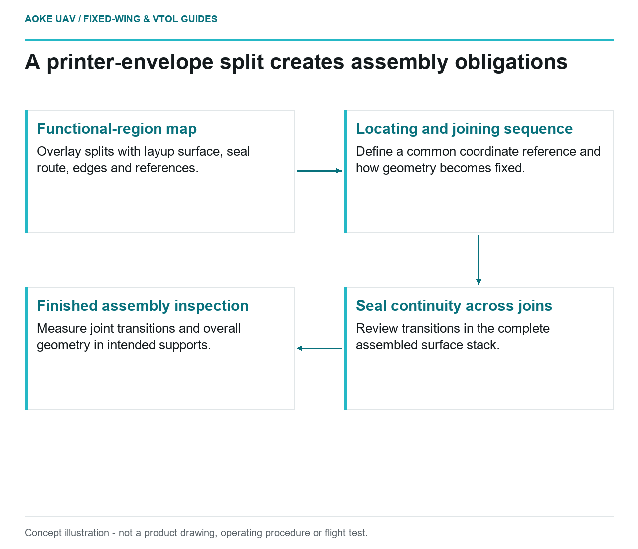
- Functional-region map: Overlay splits with layup surface, seal route, edges and references.
- Locating and joining sequence: Define a common coordinate reference and how geometry becomes fixed.
- Seal continuity across joins: Review transitions in the complete assembled surface stack.
- Finished assembly inspection: Measure joint transitions and overall geometry in intended supports.
A hypothetical tooling team needs a multi-meter wing mold for a large fixed-wing civil aircraft, but its printer cannot build the complete tool. Dividing the CAD model into printable pieces solves an envelope problem, not the whole tooling problem. This article examines the initial segmentation architecture: where to divide, how to locate the pieces and what to inspect after joining. It describes no GAUTEN tool or production result.
Joint location versus critical surface regions
Start with a map of the finished tool’s functional regions, including the layup surface, intended panel edge, bag seal route, handling features and inspection references. For this scenario, overlay several candidate parting lines and ask which operations each line complicates. Do not choose the largest pieces that happen to fit before considering their assembled function.
Stratasys describes segmentation as an option for tools exceeding the machine’s build chamber, with secondary joining operations and designed alignment features. It recommends geometrically interlocking joints rather than simple butt joints in its large-tool guidance. These recommendations concern FDM tooling, not joints in a fixed-wing airframe. [1]
In the hypothetical comparison, a split through a difficult contour might simplify printing but increase surface-restoration and inspection work. Another split might make an assembly reference inaccessible. Treat these as design-review tradeoffs, not claims that one location is always prohibited. The acceptable arrangement depends on the actual mold and process.
Alignment and assembly datums
The OEM guide identifies tongue-and-groove, dovetail and other mechanically locating arrangements as examples that aid tool assembly. It also discusses bonding and thermal welding as possible joining methods. Its examples do not constitute a joint design for an unspecified wing mold. [1]
For this fixed-wing project, define a common coordinate reference for every segment and the finished assembly. Give locating geometry, joining geometry and measurement targets different roles in the drawings. A snug mating feature can assist assembly without proving that the finished aerodynamic surface lies where intended.
Before committing to print, ask how the pieces will be held while joining, how squeeze-out or weld finishing will be managed and how the assembled reference will remain accessible. The design should identify the sequence in which geometry becomes fixed. Proposed fixture loads and joint-processing details require the actual tooling engineer’s substantiation.
Seal continuity across segments
A long mold also needs an explicit vacuum-boundary design. The Stratasys guide explains that as-built FDM tools have internal porosity and ordinarily need post-processing for vacuum integrity. It further makes sealing selection dependent on the application and compatibility with the printed material. [1]
In this scenario, draw the sealing route across every proposed joint rather than assuming the final surface coating will hide the split. Identify intersections with flanges, fittings and transitions in tool construction. Ask whether the joining and sealing instructions are mutually compatible throughout the specified cure cycle.
Do not turn the architecture review into an improvised adhesive recipe. The same guide calls for joining adhesives compatible with the tool and capable of withstanding cure temperatures. Actual product selection, preparation and acceptance need the selected supplier documentation and evidence for the complete assembly. A brand example in a guide is not a blanket substitution rule. [1]
Dimensional verification after joining
Propose inspecting the assembled mold in its intended support condition after joining and final surface work. Segment inspection remains useful, but it answers a narrower question. The finished tool’s inspection plan should explicitly include joint transitions and the relationship between local surface measurements and the overall reference system.
For the large fixed-wing project, the design handoff would contain a segment map, part identities, controlled joining sequence, accessible datums, proposed seal route and assembly-level inspection requirements. Keep the original model, print files and inspected configuration identifiable. Do not infer final accuracy by adding machine catalogue claims together.
If the tool will later be disassembled, flag that requirement while choosing the architecture. Initial joint design must allow the eventual reassembly checks to be meaningful. Detailed repeated-assembly procedures are a separate task; here the decision is whether the chosen segmentation can support them without concealing critical surfaces or references.
Related reading
- Planning Printed Molds for Sandwich Wing Skins
- Supporting Multi-Meter Composite Wings During Handling