Concept illustration
Read diagram notes
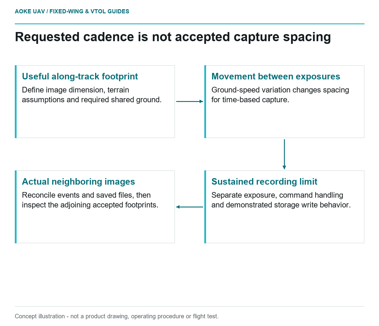
- Useful along-track footprint: Define image dimension, terrain assumptions and required shared ground.
- Movement between exposures: Ground-speed variation changes spacing for time-based capture.
- Sustained recording limit: Separate exposure, command handling and demonstrated storage write behavior.
- Actual neighboring images: Reconcile events and saved files, then inspect the adjoining accepted footprints.
Distance spacing versus time triggering
Imagine a large fixed-wing survey aircraft collecting a long block of images for a civil mapping project. Its camera has a planned overlap setting, but that setting is only a request until the integration is examined. The RedEdge-MX Revision 04 guide provides a model-specific example: timer acquisition can produce unreliable physical spacing when ground speed changes, whereas its overlap mode responds to forward distance. [3] These features are not universal camera capabilities.
For this hypothetical mission, define along-track overlap in terms of shared ground coverage between accepted images. Establish which image dimension lies along the flight line and which terrain assumptions were used. In a deliberately simplified planning model, the permitted distance between captures follows from that useful footprint and the desired shared coverage. Timing can then be checked against the ground movement between actual exposures, rather than inferred from a command rate alone.
Exposure and write-cycle limits
The same RedEdge-MX guide says capture rate depends heavily on the storage device and warns that commanding timer acquisition faster than the device can write may cause inconsistent intervals. [3] It is evidence for checking sustained capture behaviour, not a transferable throughput specification for every camera. Do not import that model’s card, interval or recommended overlap into a different fixed-wing payload proposal without its own documentation.
Ask the payload integrator to distinguish exposure duration, command handling and sustained recording capacity. For our large-area scenario, a short bench burst is not the proposed acceptance evidence for an entire survey strip. Specify a configuration-specific sustained-capture demonstration and preserve the resulting files and event records. Identify the installed storage, camera configuration and test conditions so a later media change does not quietly invalidate what the team believed it had checked.
Variable ground speed along the line
Use the planned ground-speed envelope as an acquisition question, not an aircraft instruction. In the hypothetical review, compare the largest expected movement between captures with the useful footprint and required coverage. Examine both line directions rather than selecting only the easier part of the route. If the request exceeds the demonstrated camera capacity, refer the conflict back to mission and payload design instead of assuming the aircraft can safely slow to any desired speed.
Be clear about what an automatic mode does not solve. In the cited RedEdge-MX revision, overlap mode calculates forward overlap but not side overlap; line spacing must be planned separately. [3] A large fixed-wing integration therefore needs separate evidence for capture spacing along a line and usable coverage between adjacent strips. The mode name alone is not confirmation that every part of a broad civil survey block has adequate image support.
Detect gaps in capture records
For the proposed acceptance record, reconcile commanded triggers with recorded image identifiers, timestamps and positions. Ask what each timestamp means and whether rejected or missing captures remain visible in the audit trail. Where an interval is unexpectedly long, mark the corresponding ground segment for footprint review. A trigger log without a matching image should remain an unresolved acquisition event, not be counted automatically as successful coverage.
USGS treats acquisition geometry, calibration and quality verification as linked contributors to image-product quality. [1] Apply that principle here by checking both local image support and the resulting adjustment, rather than merely counting files. Retain the capture-gap map with any reacquisition decision. The outcome of this hypothetical review is an inspectable spacing assessment for the actual installed fixed-wing payload, not a claim that the camera achieved a particular coverage or accuracy on a real flight.
An illustrative capture reconciliation would use separate fields for requested event, available camera response, saved image and accepted footprint. Do not collapse these into a single successful-trigger flag. If a sequence contains a missing saved image, identify the adjoining accepted images before deciding whether shared ground coverage remains adequate. This is a proposed audit format for the fixed-wing acquisition chain, not a claim that the cited camera provides every listed event field.
Related reading
- Exposure Time and Motion Blur in Fixed-Wing Mapping
- Camera Trigger Interfaces in a Powered Aircraft System