Concept illustration
Read diagram notes
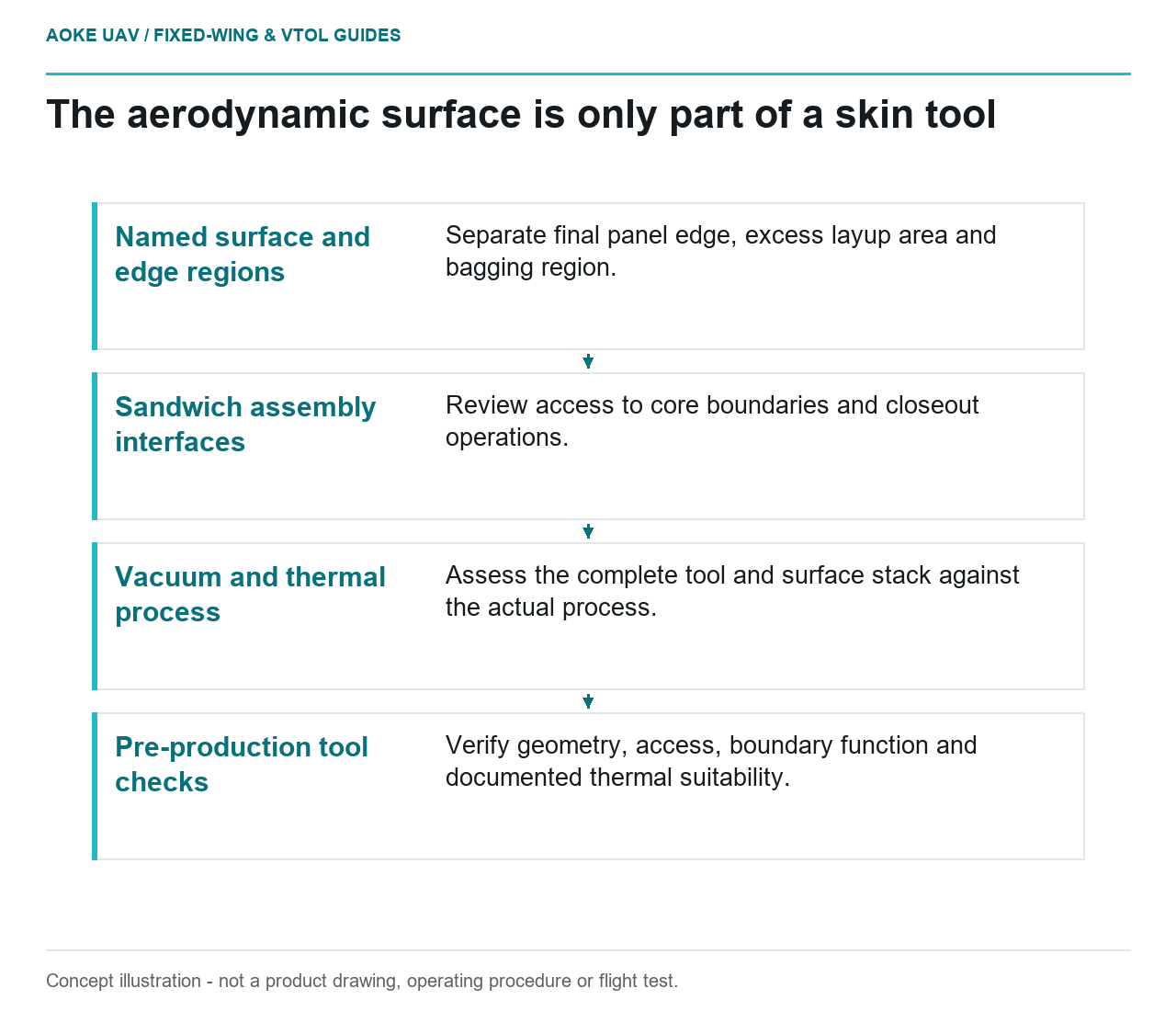
- Named surface and edge regions: Separate final panel edge, excess layup area and bagging region.
- Sandwich assembly interfaces: Review access to core boundaries and closeout operations.
- Vacuum and thermal process: Assess the complete tool and surface stack against the actual process.
- Pre-production tool checks: Verify geometry, access, boundary function and documented thermal suitability.
Imagine a printed layup mold for the broad sandwich skin of a large fixed-wing civil mapping aircraft. The visible aerodynamic surface is only one part of the tooling brief. In this hypothetical editorial scenario, the design review must also make room for material placement, edge processing, bagging, cure and inspection. It is not an GAUTEN manufacturing example or a specification for producing a flight component.
Layup surface and edge allowance
Define which surface the mold controls and which dimensions will be established later. In the proposed workflow, the tool drawing would distinguish the finished panel boundary, excess layup area and bagging region. Avoid asking a single unlabelled perimeter curve to represent all three. The responsible designer must provide the actual allowances and references.
The Stratasys guide starts its male-tool example from the desired part shape and extends the surface beyond the part edge for trimming. It separately discusses supporting features and rounding edges to protect vacuum bags. Those are process-planning concepts from an OEM FDM tooling guide, not universal dimensions for a fixed-wing skin mold. [1]
A useful design-review question is whether each operation has a defined working area without changing the intended aerodynamic geometry. If the printer envelope makes the extra area inconvenient, resolve the tooling architecture explicitly rather than quietly reducing the manufacturing allowance.
Core and closeout manufacturing interfaces
The hypothetical sandwich skin needs a manufacturing definition that explains how its facesheets, core and edge details are assembled. The mold design should be reviewed against that definition, including access to place and inspect features. Do not infer core preparation or closeout geometry from the outer surface model alone.
NASA JSC PRC-6002 distinguishes sandwich manufacturing process types and ties use of its process specification to the drawing or CAD definition. It also states that precursor materials must meet applicable material specifications. This illustrates the importance of a defined assembly process; the NASA specification is contextual and is not automatically applicable to this UAV. [4]
For this fixed-wing review, put unresolved interfaces on a shared tooling-and-part issue list. Examples include access to a core boundary, the sequence of an intermediate operation and how a panel will be removed without obscuring an edge inspection. Resolve these questions through the actual design authority rather than improvising them during layup.
Vacuum and cure-process compatibility
The Stratasys guide identifies cure temperature, thermal expansion, pressure, bagging method and sealing as tool-design inputs. It explains that FDM porosity and visible build layers typically require post-processing for vacuum integrity and surface quality. The discussion is tied to its materials and tooling constructions. [1]
Translate that into an evidence request for the proposed mold: identify the real material system’s cure envelope, the complete assembled tool, its surface stack and the intended bagging arrangement. The review must assess these together. A material family name or a room-temperature photograph cannot answer the complete compatibility question.
NASA’s sandwich process specification requires ancillary consumables, including bagging and mold-release materials, to remain chemically inert toward the part materials during processing. That is a useful contextual compatibility question, not a substitute for the chosen suppliers’ instructions or the project’s process qualification. [4]
Tool inspection before panel production
Propose separate checks for geometry, usable access, vacuum performance and documented thermal suitability before authorizing panel production. Their methods and limits need project-specific approval. Record what was measured after final finishing and joining, not merely what the original print was expected to produce.
Keep mold acceptance separate from panel acceptance. PRC-6002 explicitly treats nondestructive evaluation as a separately specified topic rather than a method supplied by that process document. A plausible mold therefore does not establish an inspection method for the resulting sandwich panel. [4]
The final fixed-wing tooling brief should leave no uncertainty about its role: it controls named manufacturing interfaces within a defined process. It does not establish laminate allowables, wing strength or aircraft release. If a required process input remains unknown, the useful engineering outcome is a recorded hold point, not a generic printing recipe.