Concept illustration
Read diagram notes
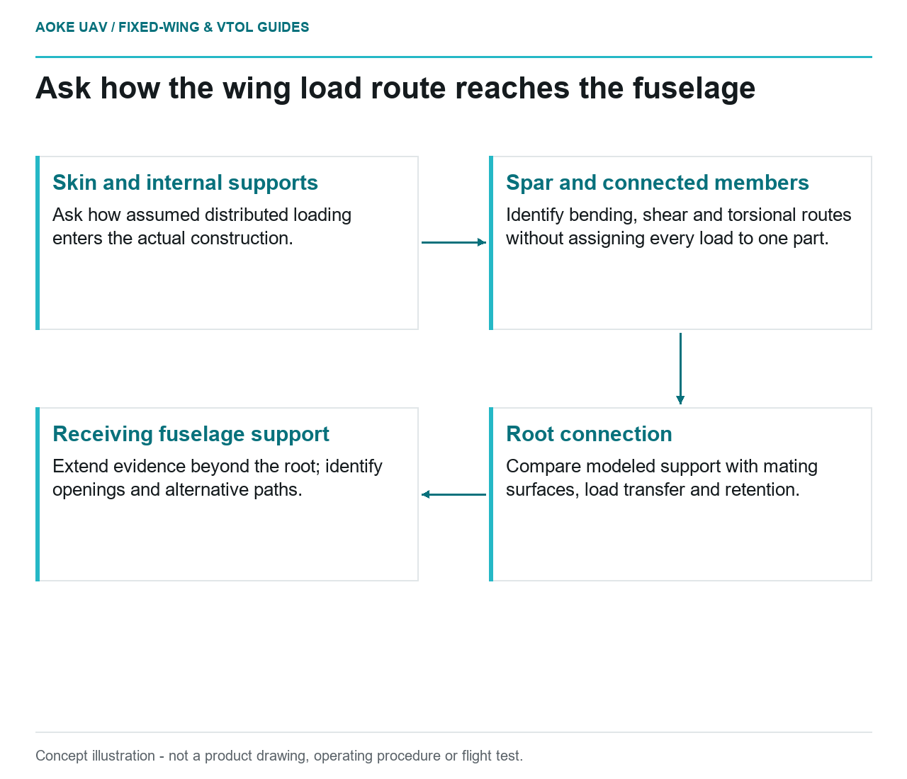
- Skin and internal supports: Ask how assumed distributed loading enters the actual construction.
- Spar and connected members: Identify bending, shear and torsional routes without assigning every load to one part.
- Root connection: Compare modeled support with mating surfaces, load transfer and retention.
- Receiving fuselage support: Extend evidence beyond the root; identify openings and alternative paths.
Read the structure as a connected route
A hypothetical multi-meter civil survey wing provides a useful review exercise: distributed aerodynamic loading must be reconciled with the reactions where the wing joins the fuselage. Instead of asking whether carbon fiber is strong, ask which parts carry each reaction and what evidence covers their interfaces. This is original integration reasoning for a large industrial fixed-wing concept, not a description of an GAUTEN design or test.
FAA composite guidance emphasizes stress concentrations, competing failure modes, out-of-plane effects and component tests representing complex load paths. Those themes support reviewing the complete assembly rather than ranking fibers from a brochure. The document concerns certificated-aircraft substantiation; it does not approve this hypothetical UAV. [1]
From skin loading to spar reactions
For the review sketch, mark the skin, internal supports, spar and root connection. Ask the designer to explain how the assumed loading reaches each member. Do not assign every load to the spar by default, or assume a smooth external shell is only aerodynamic covering. The requested deliverable is an annotated load-path drawing for the actual construction, including which interfaces are bonded, fastened or integral.
Use different colors for the designer’s identified load cases rather than drawing one attractive arrow. Ask where bending, shear and torsional reactions enter the next component, and which analysis represents the interaction. These are questions for the configuration assessment, not a substitute calculation. A reviewer without the laminate, geometry and boundary conditions cannot infer the resulting stresses from a photograph.
Do not stop at the wing root
Extend the sketch through the root fitting into the fuselage support. Ask whether the substantiation includes the receiving structure and the connection stiffness assumed by the wing model. A root fitting’s metal grade does not answer how the surrounding laminate or attachment assembly was represented. FAA guidance explicitly treats holes and joints as structural details and discusses representative material and process design values. [1]
In our hypothetical fixed-wing survey installation, the transport joint is an especially useful review boundary. Request a comparison between the modeled attachment and the assembled hardware: locating surfaces, load-bearing surfaces, retention and accessible inspection areas. If the analysis ends at an ideal support, record who is responsible for checking the real interface rather than treating the mathematical support as an actual component.
Follow the route around openings
Add payload hatches, cable passages and access panels to the same drawing. Ask what structure was removed, what alternative route is intended, and whether an installed cover is part of the assessed load-carrying configuration. Do not prescribe reinforcement from this explainer. The relevant question is whether the opening and its surroundings appear in the configuration-specific evidence.
FAA’s building-block discussion moves from simpler tests toward details, subcomponents and components, with component validation accounting for combined loads and complex load paths. A coupon result therefore does not automatically answer the hatch-interface question. [1] For the proposed aircraft, request a map connecting each sensitive detail to the analysis or test that represents it.
Separate stiffness from strength evidence
Ask for two clear explanations: what establishes the ability to carry the assessed loads, and what establishes the deformation assumed in adjacent systems. Avoid using a successful strength statement as an alignment statement for a survey payload. FAA guidance discusses environmental effects on both strength and stiffness and treats aeroelastic evaluation separately from static substantiation. [1]
For this large fixed-wing review, record the payload position, root configuration, permitted manufacturing discrepancies and environmental assumptions alongside each evidence reference. If a replacement fitting or new hatch changes one of those assumptions, flag the evidence for applicability review. This is a proposed document-control practice, not an instruction to operate a modified aircraft.
A useful review outcome
The outcome should be a connected drawing and an evidence index, not a claim that one material is universally superior. No GAUTEN loads, laminate schedules or structural allowables were supplied. Leave numerical margins and release decisions to the applicable aircraft documentation and responsible assessment; use the reading exercise to expose where those documents are still missing.