Concept illustration
Read diagram notes
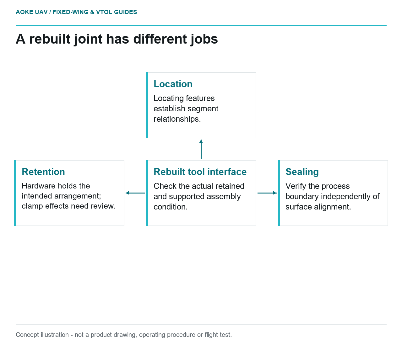
- Rebuilt tool interface: Check the actual retained and supported assembly condition.
- Location: Locating features establish segment relationships.
- Retention: Hardware holds the intended arrangement; clamp effects need review.
- Sealing: Verify the process boundary independently of surface alignment.
A segmented wing tool has been taken apart for storage and is now being rebuilt. Every section still carries the correct label. The unresolved question is whether the assembled surface and interfaces reproduce the accepted condition. In this hypothetical large civil fixed-wing workshop, the review concerns repeated assembly, not the original decision about where to split the mold into printer-sized pieces.
Locating features and clamp effects
Separate the functions of location, retention, and sealing in the assembly definition. A locating feature establishes a relationship; hardware holds an arrangement; a seal addresses a different process requirement. The proposed review should identify which features do each job and how the tool is supported during assembly. Avoid an informal instruction to tighten everything until the surface looks right.
Stratasys discusses mechanical interlocking features for tool-segment alignment and joining, and identifies bonding or thermal welding as possible secondary processes in its FDM tooling context. [3] Those examples do not demonstrate that every segmented tool is repeatedly demountable. Confirm that the actual design is intended for disassembly before adopting a rebuild procedure or treating a permanently joined interface as reusable hardware.
Seal continuity under processing conditions
The completed tool needs a sealing arrangement appropriate to its actual process. Stratasys explains that FDM tools generally need post-processing to achieve the required surface finish and vacuum integrity, with the preparation and sealing method determined by the application. [3] That establishes why a close-looking joint is not a sufficient sealing claim. It does not provide a universal leak criterion for the proposed mold.
In this fixed-wing scenario, ask the process owner what verification is required after rebuilding and under which conditions. Identify seal surfaces, transitions, local repairs, and any materials altered during separation. Keep a sealing check distinct from a geometric check: neither one should be described as proving the other. No unverified sealant substitution, bagging arrangement, or pressure setting is recommended by this article.
Surface mismatch at the join
Use the controlled assembled definition to identify where steps, gaps, or local contour changes matter to the intended manufacturing operation. The review should include the finished surface and relevant datum references, not just fastener-hole coincidence. A set of individually acceptable segments could still be assembled in an arrangement that has not been evaluated against the complete tool definition.
Proposed inspection records can distinguish loose placement, the defined retained configuration, and any later processing-state evidence requested by engineering. Record the assembly condition attached to each measurement. If alignment changes when the documented hardware is applied, preserve the observation for disposition rather than change the measurement registration until the discrepancy disappears. This is a suggested review approach, not a reported result for a real mold.
Inspection of the assembled mold
Define who releases the rebuilt set, which checks are repeated, and how unresolved deviations are controlled. Retain section identities, hardware configuration, current drawings, and the inspection outcome together. A replacement segment should return through the change-review route rather than enter the tool solely because its outline resembles the removed section. The purpose is an understandable configuration record, not unnecessary duplication of unrelated measurements.
For large fixed-wing composite tooling, repeated assembly is a manufacturing event with its own evidence needs. The OEM guide supports attention to alignment, joining, finishing, and sealing; application-specific acceptance still belongs to the responsible tooling authority. [3] Close the rebuild only for the configuration actually checked, and keep resulting airframe-part acceptance independent from the status of the ground tool used to manufacture it.