Concept illustration
Read diagram notes
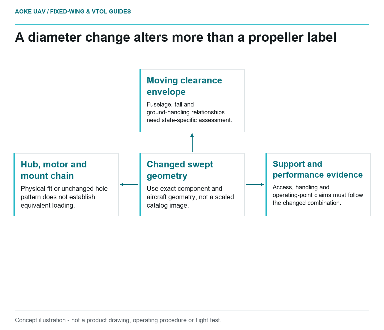
- Changed swept geometry: Use exact component and aircraft geometry, not a scaled catalog image.
- Moving clearance envelope: Fuselage, tail and ground-handling relationships need state-specific assessment.
- Hub, motor and mount chain: Physical fit or unchanged hole pattern does not establish equivalent loading.
- Support and performance evidence: Access, handling and operating-point claims must follow the changed combination.
Increasing propeller diameter is not merely editing one item in a motor comparison. For a large industrial fixed-wing aircraft, the proposal should trigger an installation review with defined geometry, structural interfaces and handling assumptions. This article provides questions for that review, not a recommended diameter, clearance distance or permission to modify an aircraft.
Trace clearance through the installed geometry
Consider a hypothetical civil fixed-wing survey aircraft with an aft propulsion installation and a proposed larger propeller. The team needs to review its relationship to the fuselage, tail and ground-handling arrangement. This is an original editorial scenario, not an GAUTEN design. Begin with the exact proposed component and the controlled aircraft geometry, not a scaled catalogue illustration.
As a proposed review method, ask for the swept geometry and the aircraft states relevant to clearance. Identify what evidence addresses movement, assembly variation and the installed configuration. Mark undocumented assumptions for the design owner. An apparent gap in a static drawing is not, by itself, a substantiated clearance envelope, and this article supplies no universal distance to fill that gap.
APC’s FAQ distinguishes propeller types and modifiers rather than treating every diameter label as the same product.[4] Its technical advisories also decline universal propeller-size recommendations across differing motors and model applications.[13] These are manufacturer-specific context, not large-UAV installation guidance. Obtain the actual component manufacturer’s requirements for the proposed combination.
Review mounts and structural interfaces
List the proposed propeller, hub, adapter, motor, mounting hardware and structural attachment in one configuration record. Ask the responsible engineers what loads and installation requirements must be reassessed when the combination changes. Do not assume that retaining the same mounting-hole pattern establishes equivalent loading, nor invent a structural allowance from the fact that a part physically fits.
FAA composite-structure guidance discusses substantiation through analysis and testing in a defined design context and emphasizes inspection and repair access.[10] It is contextual guidance for certificated aircraft structures, not evidence that this hypothetical UAV’s composite mount is adequate. Use it to frame the need for traceable structural substantiation and maintainability questions, not to claim certification or prescribe a laminate.
The review should identify who owns each interface: propulsion installation, airframe structure, control system and maintenance documentation. A larger-propeller proposal should not be accepted merely because each supplier considered only its own part. Retain unresolved load and attachment questions as explicit dependencies in the change record.
Include handling and personnel interfaces
For the survey scenario, ask how the changed geometry interacts with transport fixtures, assembly tasks, ground support and the documented recovery arrangement. Request the aircraft-specific procedures and hazard assessment that govern those activities. This is a review scope, not a generic operating procedure. Do not invent a stand-off distance, protective-device specification or assurance that a familiar handling method remains acceptable.
Keep maintenance access visible in the geometry review. If removal or inspection requires a different sequence, identify the documentation that must change. The goal is to avoid a nominally simple performance modification leaving the support configuration undefined. Any assessment of acceptable risk belongs to the actual project and its applicable requirements.
Re-establish the performance evidence chain
APC publishes different suggested rotational-speed limits by product family.[11] A limit from that page does not establish a permissible speed for an unrelated propeller, and none is transferred here. The diameter proposal needs its own applicable component limits and evidence for the motor, controller and aircraft combination.
Finally, distinguish the hoped-for performance benefit from what is substantiated. Ask for the operating-point basis, installed evidence and any associated mass or configuration changes. A larger component is not automatically a better cruise system. For large fixed-wing integration, the useful deliverable is a controlled change package: geometry reviewed, interface responsibilities assigned and evidence gaps retained before any suitability claim is made.
Related reading
- When a New Payload Requires a Structural Reassessment
- Reading Propeller RPM Limits by Product Family