Concept illustration
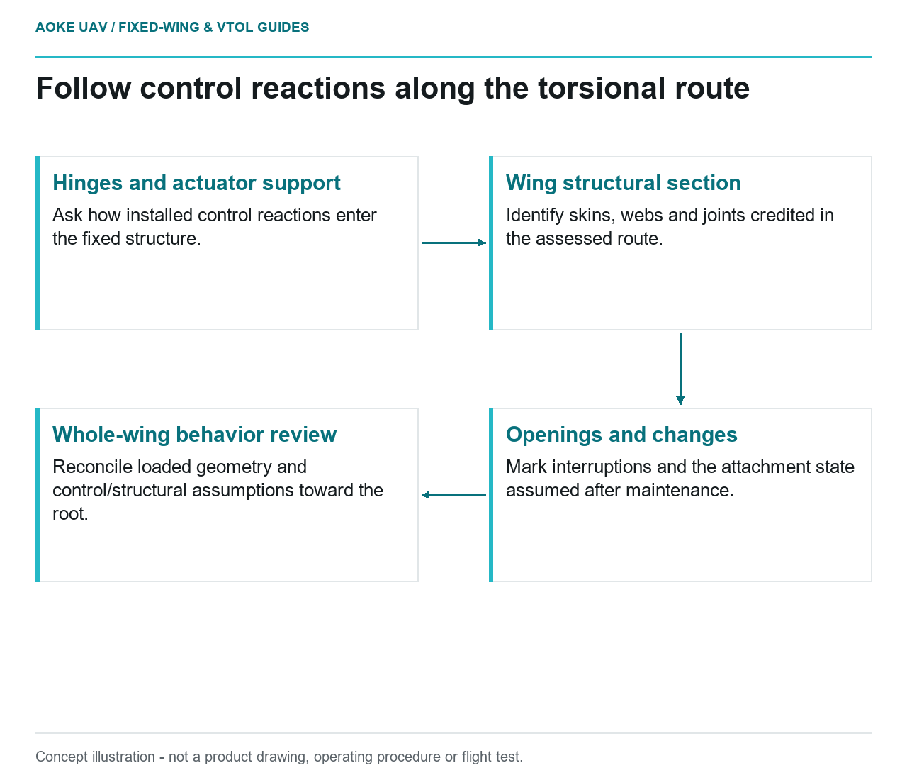
Read diagram notes
- Hinges and actuator support: Ask how installed control reactions enter the fixed structure.
- Wing structural section: Identify skins, webs and joints credited in the assessed route.
- Openings and changes: Mark interruptions and the attachment state assumed after maintenance.
- Whole-wing behavior review: Reconcile loaded geometry and control/structural assumptions toward the root.
Review the whole torsional route
Picture a hypothetical long-wing civil survey aircraft with an outboard aileron. The design review must connect the control installation to the wing’s broader structural behavior. This article focuses on that wing-section route, not on sizing a local hinge reinforcement. It is original integration reasoning for a large industrial fixed-wing concept, not an GAUTEN configuration or test report.
FAA composite guidance discusses combined loads and complex load paths in component-level validation. It separately addresses flutter, control reversal, divergence and loading-related deformation. These certificated-aircraft topics explain why a fixed drawing of a control surface is not a complete demonstration of the assembled wing’s behavior. They do not establish clearance or approval for this UAV. [1]
Identify the intended section and its boundaries
Ask the designer to show the intended torsional load path on a section and along the wing. If the concept relies on a closed structural section, identify which skins, webs and joints form that section in the assessed configuration. Do not infer closure from a continuous aerodynamic fairing or assume every removable cover participates structurally.
For the hypothetical fixed-wing review, follow that identified route from the outboard control region toward the root. Mark changes of construction, joints and major interruptions. Ask which analyses and tests represent those details together. This is a way of organizing evidence requests, not a calculation of torsional stiffness from an exterior profile.
Include hinge and actuator reactions
Request an explanation of how the control surface’s reactions enter the fixed structure through hinges and actuator support. Ask where those reactions reach the wing’s primary members and whether the model uses the same support arrangement as the installation drawing. Keep the control hardware and its receiving structure within the review boundary.
The local hinge attachment deserves its own detail assessment, but this article’s question extends beyond it: what happens to the load route across the long wing? A strong-looking bracket does not answer the behavior of the full section. FAA’s structural substantiation discussion distinguishes detail and subcomponent evidence from component validation involving combined loads. [1]
Ask who owns the interface between control-system assumptions and structural assumptions. Record any difference between a rigid support represented in one analysis and the support assessed elsewhere. The purpose is to expose incompatible assumptions, not to prescribe an actuator or operating setting.
Inspect access-panel assumptions
Locate service openings near the relevant route. For each opening, ask whether the assessed structure includes a cover, which attachment arrangement is represented and what configuration is required after maintenance. Do not assume a closed exterior outline means that the structural section has been restored.
FAA identifies holes and joints as structural details and emphasizes that manufacturing and test configurations should represent the production structure. [1] For this wing, request a configuration note that connects the opening, adjoining structure and installed attachment to the evidence. An unspecified change in cover fastening should not disappear from the document review simply because the opening is small.
Distinguish loaded geometry from the drawing
As an editorial review exercise, compare the nominal hinge line and actuator support drawing with the deformation assumptions used in the structural assessment. Ask which relationships matter to the control-system review and which have been evaluated. Do not invent an allowable twist angle or assume a particular control effect from geometry alone.
FAA’s aeroelastic section includes control reversal and divergence as well as flutter, and it discusses stiffness, mass and damping changes from service exposure and damage. It notes that residual strength can remain adequate while stiffness loss or mass increase adversely affects aeroelastic characteristics. [1] Static strength evidence therefore does not, by itself, settle all questions raised by this control installation.
Request the aircraft-specific boundary
A useful summary should identify the wing configuration, control installation, assessed conditions, supporting analyses and tests, and changes that require further applicability review. Keep that summary distinct from release instructions. No GAUTEN torsional properties, actuator loads or aeroelastic limits were supplied.
For the large fixed-wing survey concept, the completed review should connect local reactions to whole-wing behavior without pretending that a diagram establishes a margin. Use the related aeroelastic article to refine the evidence request; do not treat either explainer as a flight envelope or a substitute for responsible aircraft engineering.