Concept illustration
Read diagram notes
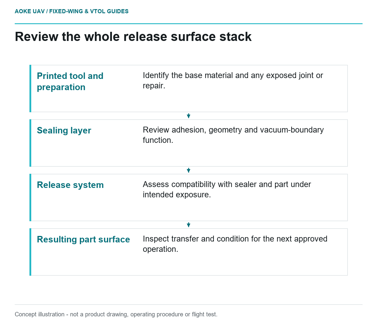
- Printed tool and preparation: Identify the base material and any exposed joint or repair.
- Sealing layer: Review adhesion, geometry and vacuum-boundary function.
- Release system: Assess compatibility with sealer and part under intended exposure.
- Resulting part surface: Inspect transfer and condition for the next approved operation.
Before a composite layup touches a printed mold, a hypothetical large fixed-wing civil-aircraft project reviews the complete surface stack: printed tool, preparation, sealer and release system. The question is compatibility in the intended process, not which coating is most familiar in the workshop. This is original editorial reasoning, not an GAUTEN layup procedure or validated material combination. No universal coating recipe or flight-panel acceptance criterion is supplied.
Tool material and sealing layers
Stratasys describes FDM tooling as requiring post-processing for surface finish and vacuum integrity. Its sealing discussion calls for compatibility with the printed material, adequate cure-temperature capability and consideration of tool life. Those conditions make the sealer a functional part of the tooling system rather than a cosmetic finish. [1]
For the hypothetical fixed-wing mold, list the actual material identities and supplier documents layer by layer. Include any segment-joint material or repair that reaches the working surface. A record saying only ‘printed polymer with release coating’ leaves the reviewer unable to connect the proposal to the available evidence.
Distinguish the intended role of each layer. The team should know what establishes the surface geometry, what provides the selected vacuum boundary and what assists separation. Where a product has several claimed functions, obtain documentation for the actual configuration rather than assuming one successful function proves the others.
Release system and cure conditions
The OEM guide places release-agent application after sealing in its general tool-preparation discussion. It describes different sealing approaches, including epoxies and adhesive-backed films, and makes application conditions important to their use. Its guidance is process- and material-specific, not approval for combining arbitrary products from those categories. [1]
For this large fixed-wing scenario, ask the selected suppliers to address compatibility of the proposed release system with the actual sealer and part material under the intended cure process. Preserve the relevant instructions and revisions. Do not translate a product’s name or broad temperature claim into evidence for the whole stack.
Also specify how repeated use will be controlled. The Stratasys cycling discussion reports degradation of a particular sealer under its tested conditions and notes that further work is needed on long-term capability. That example supports reviewing surface-system life separately from the base tool; it does not establish a service interval for this project. [1]
Surface contamination and transfer
Use the hypothetical review to define what would count as an unacceptable surface result for the intended panel and subsequent operations. Questions include whether residue is transferred, whether the finish is damaged during separation and whether the surface remains suitable for its next approved manufacturing step. These are proposed evaluation questions, not claims about a particular chemical interaction.
The guide describes adhesive-backed films as alternatives with geometry and durability limitations, including damage and adhesion concerns over use. It also describes loss of sealer adhesion in its extended cycling example. These are reasons to examine the resulting surfaces and the tool after separation rather than recording only that demolding occurred. [1]
For the fixed-wing project, keep test observations specific: which surface, which configuration, which process and what inspection method. A photograph of a released panel cannot establish chemical compatibility or later bonding suitability on its own. Those determinations need the actual acceptance requirements and substantiating evidence, not an inferred absence of trouble.
Small-scale process validation boundaries
A proposed small-scale evaluation should reproduce the compatibility question it is meant to answer. Identify the represented tool material, prepared surface, sealer, release system, part material and intended process conditions. The responsible engineer must define the methods and limits; this article does not prescribe a trial layup or any cure settings.
State what the exercise leaves out. A flat development sample may not represent a deep contour, a segment transition, handling damage or the history of a reused full-scale mold. The OEM guide itself ties material and sealing selection to application and anticipated life, which argues against treating one convenient sample as blanket evidence. [1]
The final record should connect the accepted stack to the controlled manufacturing instructions and identify changes that reopen review. Acceptance of the tool surface remains separate from acceptance of the composite panel and release of the fixed-wing aircraft. A clean separation is an observation; a qualified manufacturing process requires a much more explicit evidence boundary.