Concept illustration
Read diagram notes
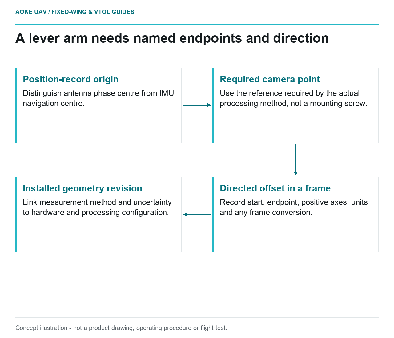
- Position-record origin: Distinguish antenna phase centre from IMU navigation centre.
- Required camera point: Use the reference required by the actual processing method, not a mounting screw.
- Directed offset in a frame: Record start, endpoint, positive axes, units and any frame conversion.
- Installed geometry revision: Link measurement method and uncertainty to hardware and processing configuration.
Navigation antenna and camera reference centers
A hypothetical large fixed-wing survey aircraft carries a navigation antenna above the fuselage and a camera in a lower payload bay. Which location does its position record represent? NovAtel’s SPAN documentation distinguishes GNSS positions referenced to an antenna phase centre from INS records referenced to the IMU navigation centre; additional cameras require their own location and orientation information. [10] The first integration task is therefore to identify the actual endpoints, not merely record a distance between two housings.
For this scenario, create a reference-point drawing showing the antenna, navigation unit and camera point required by the selected processing method. Identify each point using the applicable device documentation and installation record. Keep the phase centre distinct from an arbitrary place on the antenna enclosure, and the required camera reference distinct from an accessible mounting screw. This proposed drawing is not evidence that the installed locations have already been surveyed.
Body frame and axis conventions
The NovAtel SPAN interface describes a lever arm from the IMU navigation centre to the primary antenna phase centre measured in the IMU frame, separately from the rotation relating the IMU and vehicle frames. [8] Its broader documentation also describes frame-dependent translation and rotation settings. [10] These are concrete examples of why a measured offset needs direction, axis definitions and a declared frame, not just three unsigned dimensions.
In the hypothetical fixed-wing review, write the start point, endpoint, positive directions, units and reference frame beside every offset. Then have another reviewer trace one endpoint transformation against the drawing and actual installation. If the aircraft CAD frame and navigation-unit frame differ, require an explicit conversion rather than relabelling the same numbers. Do not import the cited receiver’s axis convention or commands into another system without its applicable documentation.
Rigid mounting and installation records
The large industrial fixed-wing payload bay is the configuration being assessed, not an idealised CAD assembly. Request an installed measurement record that identifies the actual camera mount, antenna and navigation unit, along with the method and uncertainty assigned to the geometry. Use photographs or installation identifiers to connect the record to the hardware reviewed. A nominal drawing may guide that work but should not be described as proof of airborne installed geometry.
NovAtel’s OEM7 lever-arm calibration guidance recommends survey measurement where practicable and cautions against overly optimistic uncertainty inputs. [7] That is model-specific navigation guidance, not a structural qualification method. For our hypothetical aircraft, refer questions about mounting stability or configuration change to the responsible integration team. Do not invent an allowable fuselage deformation, mount stiffness or offset tolerance merely because the payload is intended for surveying.
Changes requiring updated calibration
The same OEM7 guidance requires the lever arm to be redefined after the system is remounted or the IMU or antenna is moved. [7] Apply the underlying configuration-control question to this fictional fixed-wing survey: which installation changes require the geometry record to be checked again? Identify camera remounting, antenna relocation or replacement mounting hardware as review triggers, while leaving the exact required action to the applicable system procedure.
Finish the installation package with a revision identifier shared by the drawing, measured offsets and processing configuration. Preserve superseded values so a later mapping assessment can establish which geometry was used. Separate this mechanical reference-point review from electronic time synchronisation and data-protocol verification; both deserve attention, but they answer different questions. A traceable lever arm makes the position transformation inspectable. It does not independently prove camera calibration, installed structural performance or the accuracy of the final civil mapping product.
For the hypothetical installation drawing, use labelled arrows rather than an unqualified three-number offset: name the starting centre, destination centre and frame on the drawing itself. Attach the measurement record and processing configuration revision to that drawing. If a reviewer cannot determine the direction of the transformation without consulting an undocumented convention, the record is incomplete. This is a documentation acceptance test, not a substitute for measuring the installed geometry or validating the navigation configuration.