Concept illustration
Read diagram notes
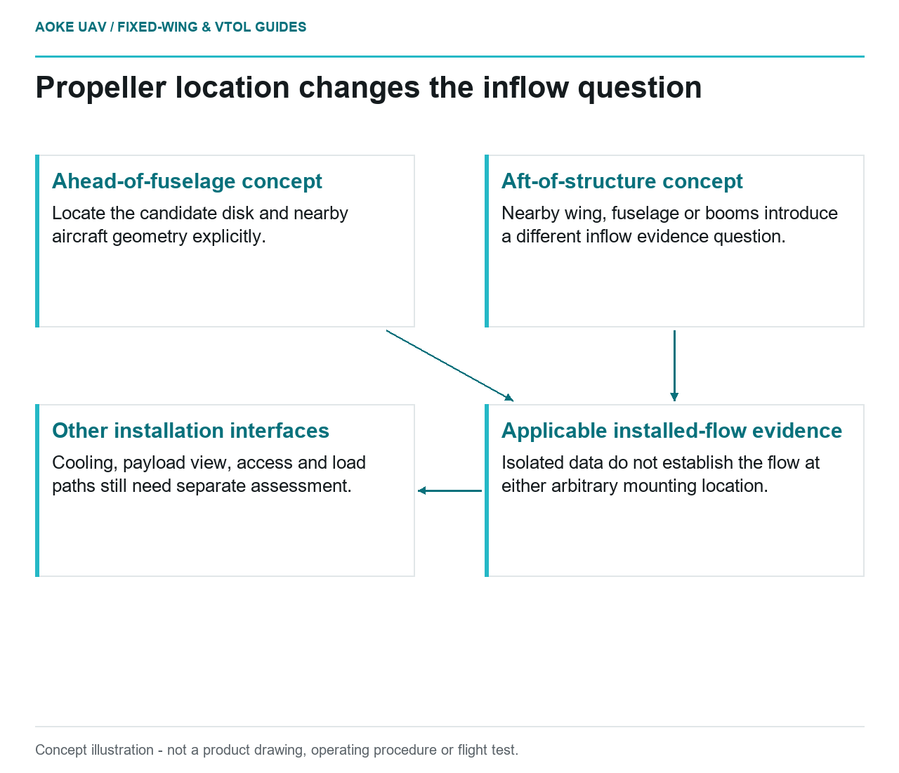
- Ahead-of-fuselage concept: Locate the candidate disk and nearby aircraft geometry explicitly.
- Aft-of-structure concept: Nearby wing, fuselage or booms introduce a different inflow evidence question.
- Applicable installed-flow evidence: Isolated data do not establish the flow at either arbitrary mounting location.
- Other installation interfaces: Cooling, payload view, access and load paths still need separate assessment.
Treat location as part of the propulsion question
Imagine a hypothetical large fixed-wing aircraft intended for civil corridor mapping. Its integration team is considering the same candidate propulsion concept ahead of the fuselage or behind nearby structure. This is an editorial comparison, not an account of a tested aircraft. The useful opening question is not which arrangement wins, but what changes between the two complete installations and what evidence would distinguish those changes.
APC describes its published performance data as analytical and identifies a standard-atmosphere basis for power, torque and thrust calculations. Those conditions should travel with any figure copied into a design discussion; they do not describe the flow at an arbitrary airframe mounting location. The manufacturer also declines general propeller-size recommendations because motor and application characteristics vary. [1]
For this hypothetical review, draw the candidate propeller disk and nearby wing, fuselage, booms and openings. Mark where the team needs evidence about incoming flow rather than assuming the isolated propeller data answer that question. Keep this drawing a question map, not a prediction of losses.
Separate inflow evidence from naming conventions
The UIUC database explicitly concerns wind-tunnel measurements of propellers for small UAVs and model aircraft. Its discussion identifies distinct thrust and torque measurement arrangements. These are useful examples of documented measurement provenance, not evidence that a large installed pusher or tractor will reproduce a database curve. [2]
Ask whether candidate evidence represents an isolated propeller, a partial airframe model or the intended installation. Then ask which forward-flight conditions and attitudes it represents. If the available record omits nearby structure, record that omission. Do not fill it with an assumed efficiency penalty, a presumed benefit from unobstructed flow or a rule that one layout is always quieter.
APC uses a pusher designation within its part-number system and also discusses reverse rotation for electric propellers. A catalog suffix therefore needs interpretation in the manufacturer’s own nomenclature. It cannot, by itself, establish how a propeller interacts with a particular fuselage or which aircraft arrangement is preferable. [1]
Review cooling and payload interfaces separately
In the proposed mapping-aircraft comparison, create a separate cooling evidence request for each location. Ask where air enters and leaves the motor and controller installation, what temperatures would be measured and which flight phases the proposed demonstration covers. Neither cited propeller source supplies an installed motor thermal qualification. A favorable propeller comparison should not silently close the cooling question.
Also sketch the payload viewing envelope, service access and cable routes. These are original review prompts for the hypothetical aircraft. If either layout puts a propeller, support or access panel near the imaging system, request a coordinated assessment rather than claiming the layout necessarily degrades imagery. The same principle applies to mechanical clearances and load paths: identify the interface and the responsible evidence, without inventing allowable distances or structural limits.
For a fixed-wing VTOL derivative, include the intended transition configuration in that evidence request. Do not assume a cruise-only comparison represents every configuration in which propulsion and payload hardware must coexist.
Make the comparison traceable and conditional
A practical comparison sheet can place each installation beside its evidence status: geometry identified, inflow conditions documented, shaft measurements available, thermal assessment available and payload interface reviewed. This is a proposed editorial method, not a qualification checklist from the cited sources. Its purpose is to make unlike evidence visible before the team draws a conclusion.
Use the same named quantities and comparable conditions wherever a comparison is possible. Where it is not, state the difference and retain the open question. For this large civil fixed-wing scenario, the defensible outcome may be a targeted request for installed-system evidence rather than a selection. Small-propeller measurements and analytical catalog data can help formulate that request; neither establishes a universal ranking of pusher and tractor arrangements.
Related reading
- Reading the Load Paths in a Large Composite UAV Wing
- Vibration and Image Quality in Fixed-Wing Payloads