Concept illustration
Read diagram notes
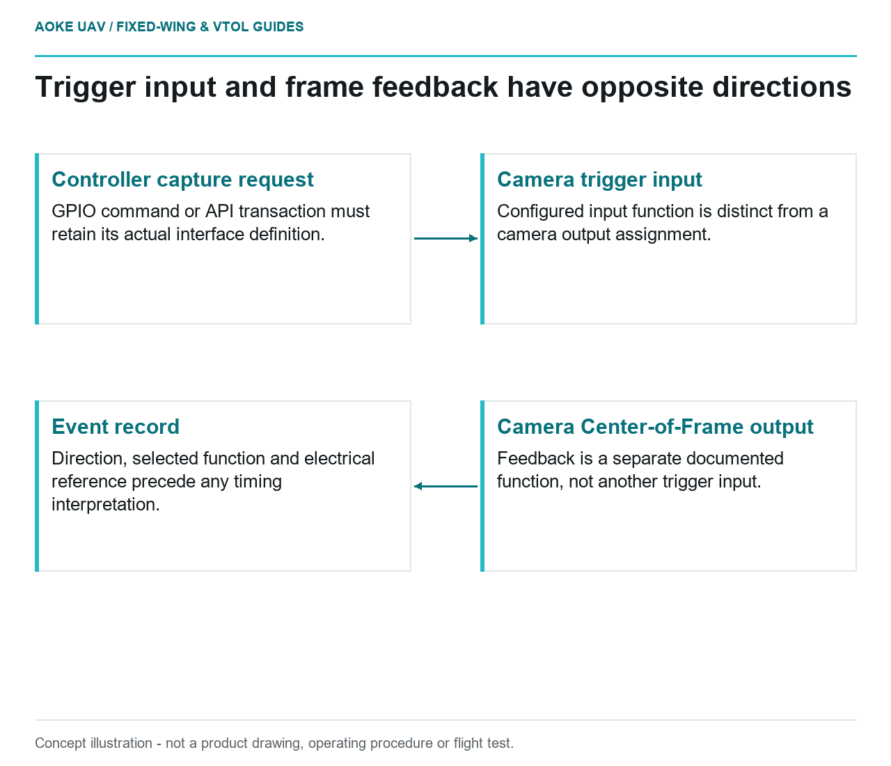
- Controller capture request: GPIO command or API transaction must retain its actual interface definition.
- Camera trigger input: Configured input function is distinct from a camera output assignment.
- Camera Center-of-Frame output: Feedback is a separate documented function, not another trigger input.
- Event record: Direction, selected function and electrical reference precede any timing interpretation.
Consider a hypothetical large industrial fixed-wing mapping aircraft whose controller connects to a RedEdge-P camera. The proposed harness labels one conductor camera trigger, but the configuration sheet does not say whether that conductor receives commands or transmits feedback. That omission matters before anyone discusses geotag precision. This worked interface review uses the December 2021 RedEdge-P and DLS 2 guide, revision 01; it is not an GAUTEN installation or a wiring prescription for another camera.
Signal level and interface definition
The guide assigns three configurable GPIOs on the COMM connector to functions including trigger input and Center-of-Frame output. Its IO table distinguishes nominal 3.3 V operation, a 0–5.0 V range and a 5.1 V absolute maximum. These are different specification categories, not three alternative design targets.[1] The aircraft interface review must therefore identify the selected function and the applicable electrical limits together, rather than accept a connector merely because it fits.
| Documented interface | Direction and integration meaning |
|---|---|
| Configured trigger GPIO | Input to camera: the aircraft requests capture through the selected external-trigger function.[1] |
| Configured Center-of-Frame GPIO | Output from camera: a feedback function, not a second trigger-command input.[1] |
| API capture command | A communications transaction: HTTP capture requests or serial MAVLink commands use their documented data interfaces, not a GPIO pulse.[1] |
In the hypothetical drawing, connecting the controller’s command output to a camera GPIO assigned as an output would confuse the roles at both ends. Conversely, selecting an input function does not establish that the controller’s signal levels and reference arrangement are compatible. The functional assignment and electrical assessment are separate decisions; neither follows from the word trigger.
Power-state and startup behavior
The guide requires the supply specification to be met at the camera power port after wiring losses. Its power section also cautions against joining distinct power-source and trigger grounds at the camera and discusses isolation in that situation.[1] This is a model-specific reference problem, not a universal instruction to isolate every payload or join every ground.
There is a further document-reconciliation issue: the external-trigger section refers to an isolated ground connection, while the power caution discusses separate systems and internally joined power-ground pins.[1] A harness release must resolve those passages with the applicable connector definition and OEM clarification. The companion article on signal grounds and power returns addresses that reference map; this article does not choose an isolator or publish a replacement pinout.
For the large fixed-wing example, distinguish three proposed acceptance records: supply compliance, confirmed interface configuration and camera readiness. A passing supply check would not answer the other two. No fixed startup delay is inferred here; the supplied interface tables do not establish a complete readiness sequence for this aircraft.
Trigger command versus exposure event
The guide offers rising-edge, falling-edge and PWM-transition triggering; it separately describes API capture requests.[1] These options explain why a generic controller output cannot be selected solely by the label camera trigger. They do not establish one universal pulse recipe, feedback waveform or command-to-exposure delay.
Keep timing handoff short and explicit: record which channel issued the request and which documented camera event, if available, supplied feedback. Image-event association and clock interpretation belong to the related event-timing article. Here the electrical deliverable is an unambiguous input/output/API distinction, not another timestamp audit.
Model-specific verification and records
The hypothetical fixed-wing interface sheet would pair each signal’s selected function with direction, voltage specification, reference resolution and document revision. A connector-assembly aid can preserve a reviewed harness arrangement, but cannot decide those properties. Changing the GPIO assignment would reopen the functional comparison even if the cable remained untouched; changing the power source would reopen the reference comparison even if the assignment stayed unchanged.
This review does not demonstrate an installed camera’s compatibility. It identifies concrete reasons two apparently similar trigger connections can represent different interfaces, and what must remain unresolved until the exact camera, controller and harness evidence agree.
Related reading
- Camera Event Timing and Geotag Quality
- Printed Connector Assembly Aids for Payload Harnesses
- Signal Grounds and Power Returns in UAV Payload Integration