Concept illustration
Read diagram notes
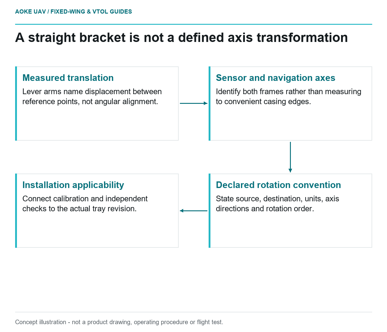
- Measured translation: Lever arms name displacement between reference points, not angular alignment.
- Sensor and navigation axes: Identify both frames rather than measuring to convenient casing edges.
- Declared rotation convention: State source, destination, units, axis directions and rotation order.
- Installation applicability: Connect calibration and independent checks to the actual tray revision.
A sensor can sit squarely in a payload bay without its measurement axes matching the navigation frame used in processing. The practical question is not whether the bracket looks straight, but whether the recorded relationship describes the installed system. This article uses a hypothetical large fixed-wing civil corridor survey with a removable camera or LiDAR tray. It is an integration review example, not an aircraft qualification or an observed GAUTEN result.
Mechanical mounting versus sensing axes
Keep translation and rotation in separate records. A lever arm describes displacement between named reference points; an angular alignment describes how one set of axes relates to another. The official Inertial Explorer documentation illustrates this distinction by treating the IMU-to-antenna offset separately from body-to-IMU rotations. Its particular frame definition is an example, not a universal aircraft convention. [8]
For the hypothetical tray, ask the installer to identify the navigation reference, sensor reference and mount reference on a drawing. Then ask which of those relationships is physically measured, which is supplied by the manufacturer and which is estimated through calibration. A measurement to a convenient casing edge should not silently become a measurement to an optical or navigation origin. Keep the underlying drawing beside the processing configuration rather than relying on a verbal description.
State the orientation convention
A complete alignment record needs more than three unlabeled angles. Name the source frame, destination frame, axis directions, angular units and rotation convention expected by the selected software. Inertial Explorer explicitly documents an order for its body-to-IMU rotations, demonstrating why a set of values cannot safely be moved between interfaces merely because both offer roll, pitch and yaw fields. [8]
In this scenario, the integration team would review a diagram showing the fixed-wing fuselage, navigation unit and payload axes together. If the sensor is installed backwards for packaging reasons, that fact should be explicit. The engineer should trace the transformation into the delivered trajectory or sensor model before judging a numeric calibration result. No generic boresight tolerance is proposed here: acceptance belongs to the actual instrument procedure and the civil project’s uncertainty requirements.
Calibration evidence and repeatability
For its own 3DEP lidar context, the USGS deliverables specification calls for a summary of sensor calibration, boresight processing, subsequent swath adjustment and supporting geometric-quality analyses. That is a useful example of an evidence chain, not a requirement automatically imposed on every UAV survey. [4]
For the hypothetical fixed-wing collection, request the applicable sensor-specific calibration method before designing the check flight. Record the installed configuration and the observations used to estimate alignment, then retain separate observations for judging the resulting product. A report should distinguish an estimated angular parameter from evidence that the corrected dataset meets its intended use. Neither a visually smooth mosaic nor a small image pixel spacing should substitute for that distinction.
USGS imagery guidance separates ground sample distance from geometric accuracy and emphasizes the contribution of control and tie-point quality. Accordingly, a finer planned GSD would not, by itself, verify this mount’s alignment or guarantee map accuracy. [1]
Remounting is a configuration decision
Suppose the large fixed-wing aircraft is transported with the tray removed. Before its next civil mission, compare the installation with the calibration configuration: tray identity, interface seating, fastener arrangement, sensor identity and any intervening repair. These are proposed review questions, not evidence that every removal requires the same calibration operation. Ask the instrument supplier which changes invalidate its procedure and document the answer.
A useful handover would contain the measured translation record, the angular transformation definition, the calibration report, independent product checks and a dated configuration history. If a repeat installation cannot be shown to match the calibrated arrangement, mark alignment applicability unresolved rather than quietly retaining an old file. This keeps mechanical repeatability, sensor calibration and project acceptance as three visible decisions instead of collapsing them into the statement that the payload was mounted straight.
Related reading
- Lever Arms in Fixed-Wing Payload Integration
- Removable Payload Trays Without Hidden Structural Assumptions