Concept illustration
Read diagram notes
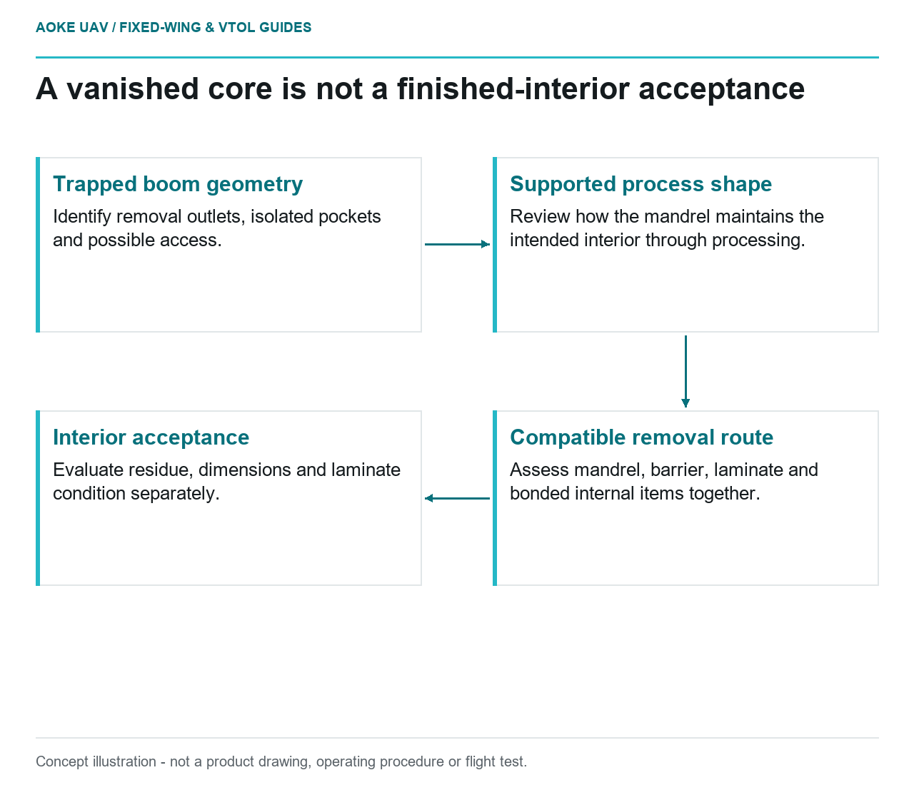
- Trapped boom geometry: Identify removal outlets, isolated pockets and possible access.
- Supported process shape: Review how the mandrel maintains the intended interior through processing.
- Compatible removal route: Assess mandrel, barrier, laminate and bonded internal items together.
- Interior acceptance: Evaluate residue, dimensions and laminate condition separately.
A closed boom can be straightforward to model and awkward to manufacture. In this hypothetical integration study, a large industrial fixed-wing survey aircraft needs a hollow composite tail boom with an internal transition that prevents a rigid tool from sliding out. The proposal is a printed sacrificial mandrel, not a printed flight structure. No GAUTEN aircraft, manufacturing trial or demonstrated performance is implied.
Start with the trapped geometry
Stratasys distinguishes soluble sacrificial tooling from a different support material that requires mechanical removal after treatment. Its discussion addresses trapped hollow composite geometry, not a universal removal method for printed plastics. [1]
For the proposed fixed-wing boom, first draw the complete removal route. Identify where material can leave, where cleaning media can enter, and which internal pockets would remain isolated. A closed shape in the finished aircraft does not require every manufacturing opening to be absent throughout production. Whether temporary access can be incorporated is a separate structural design decision, not permission to drill an unspecified hole later.
Compare the sacrificial concept against a removable mandrel before committing. The meaningful distinction is whether the proposed geometry can release without loading the new composite walls in an uncontrolled way. If a small design change creates a legitimate extraction path, a disposable core may no longer be the best answer. If the transition remains trapped, removal evidence becomes a design input rather than a cleanup note.
Support the shape through processing
The OEM guide treats tooling material, thermal behavior and tool construction as linked decisions. Its examples are specific to its FDM tooling systems and materials. They do not establish allowable conditions for an unspecified UAV laminate. [1]
Our suggested review would follow the mandrel from printing through layup, handling and the proposed composite process. Ask which surfaces define the boom interior, how the ends are located, and how the tool is supported before the laminate can carry its own shape. Review local transitions as well as the long straight region. A visually convincing unloaded print is not the proposed acceptance test.
For a multi-meter fixed-wing boom, handling also belongs in the plan. Define a supported transfer arrangement and inspection datums before a trial article is wrapped. Record the intended thermal and mechanical exposure from the actual laminate process documents. Do not obtain a cure cycle by copying an OEM tooling example, and do not substitute the generic word soluble for a documented material identity.
Removal is a compatibility problem
The guide’s separate soluble and mechanically removed examples are a warning against treating sacrificial as synonymous with water-removable. [1] For this hypothetical boom, require a compatibility assessment covering the mandrel, any barrier or sealing layer, the cured laminate and anything already bonded inside. The evidence should address the proposed removal exposure and subsequent cleaning, not simply whether an isolated printed sample disappears.
Plan how the team will recognize incomplete removal. An outlet that runs clear is not our proposed proof that every internal branch is empty. Identify likely residue traps on the drawing, decide which can be observed directly, and specify what evidence will be needed where access is limited. Avoid introducing a removal chemical or mechanical scraping method without an applicable approved process.
Accept the finished interior, not the vanished tool
The recommended trial deliverable is an interior acceptance record tied to the boom drawing. Separate dimensional findings, residual-tool findings and laminate-condition findings. A sacrificial core being absent answers only one of those questions. Inspection access, method suitability and acceptance limits still need application-specific definition.
A useful decision gate would require a representative manufacturing demonstration before committing the large fixed-wing assembly to this route. Preserve material identity, tool build revision, removal history and the resulting inspection record. If an important internal region cannot be cleaned or assessed with a defensible method, revise the geometry or stop the proposal. None of the cited OEM guidance constitutes UAV approval, laminate allowables or a ready-to-use process recipe.
Related reading
- Tail-Boom Joint Alignment and Composite Interfaces
- Reusable Segmented Printed Mandrels for Open-Ended Composite Parts