Concept illustration
Read diagram notes
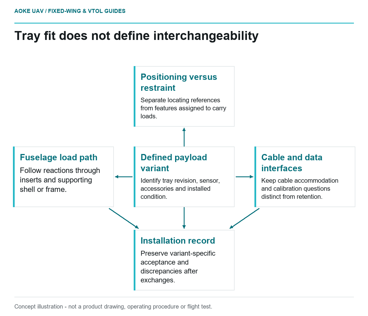
- Defined payload variant: Identify tray revision, sensor, accessories and installed condition.
- Positioning versus restraint: Separate locating references from features assigned to carry loads.
- Fuselage load path: Follow reactions through inserts and supporting shell or frame.
- Cable and data interfaces: Keep cable accommodation and calibration questions distinct from retention.
- Installation record: Preserve variant-specific acceptance and discrepancies after exchanges.
A tray that fits a bay is not necessarily an interchangeable structural installation. In this hypothetical large fixed-wing survey aircraft, an RGB camera tray and a multispectral tray share the same fuselage opening. The original editorial question is which interfaces must remain controlled when the sensors are exchanged. Nothing here describes an actual GAUTEN payload, demonstrates an approved mounting arrangement, or supplies a universal retention design.
Primary restraint versus positioning features
Begin the proposed interface review by separating positioning from restraint. Label the features intended to locate the camera and those intended to transfer its loads. A locating pin, rail, or convenient connector should not receive an assumed structural function simply because it helps the tray seat consistently. Ask the designer to define each feature’s intended role and its evidence.
FAA composite guidance treats joints and other structural details as part of the substantiation problem and calls for assessment of critical loading conditions. It does not provide allowable loads for a generic removable payload tray. [1] For this fixed-wing scenario, request drawings that distinguish locating references, retention hardware, supporting inserts, and the surrounding shell or frame. That makes assumptions visible before comparing the two payload variants.
Loads into the fuselage structure
Follow the proposed force path beyond the tray itself. Ask how the sensor’s mass and position are represented, how each restraint reacts the relevant loading, and where those reactions enter the fuselage. Compare the two complete installations, including accessories, rather than comparing the camera nameplates alone. The requested comparison should identify any change in mass distribution or center-of-gravity assumptions for the aircraft.
The FAA guidance explains why detail-level analysis and tests should represent the construction and loading being substantiated. A strong tray panel would not, by itself, establish the adequacy of its adjacent composite attachments. [1] For the hypothetical large fixed-wing mapping platform, ask whether the available report covers the actual tray, supporting structure, installation condition, and intended payload configuration together.
Connector and cable accommodation
Treat cables and connectors as a separate installation interface with explicit accommodation, not as unacknowledged restraints. For this scenario, request an installation drawing showing cable routes, service access, connector engagement, and the clearance assumed when the tray is installed or removed. These are proposed review questions, not evidence that a particular routing or connector has already passed a flight assessment.
Sensor interchange also raises a data-quality question distinct from structural retention. USGS calibration guidance addresses geometric and radiometric calibration and acquisition quality control, emphasizing traceability rather than assuming consistent results from different sensors and processing methods. It is a research-data guide, not a payload mounting standard. [3] Keep the structural installation record and the sensor calibration or data-quality record linked, while avoiding the claim that either record proves the other.
Repeatable installation records
Propose an installation record that names the aircraft, tray revision, sensor and accessories, retention configuration, and applicable inspection instructions. Record any discrepancy or substitution against the intended interface. The purpose is to let a later reviewer reconstruct what was fitted, not simply to collect a signature saying the camera was changed. FAA guidance supports manufacturing and maintenance traceability in its own certification context. [1]
For repeated large fixed-wing civil survey deployments, ask how replacement trays are identified and how configuration-specific acceptance is established. A common outer shape should not become an undocumented expansion of the accepted payload family. Where the same locating references also support data processing assumptions, ask the survey team to identify any checks needed after a change; the USGS guide supports calibration and quality-control planning, not a universal recalibration interval. [3]
Decision boundary
A credible interchangeable interface has defined roles, a documented load path, and an installation history that distinguishes variants. Request configuration-specific mounting acceptance from the responsible authority for the aircraft. This article cannot establish a payload mass limit, a restraint torque, or survey accuracy. For this fixed-wing example, physical fit is the beginning of the evidence review, not its conclusion.