Concept illustration
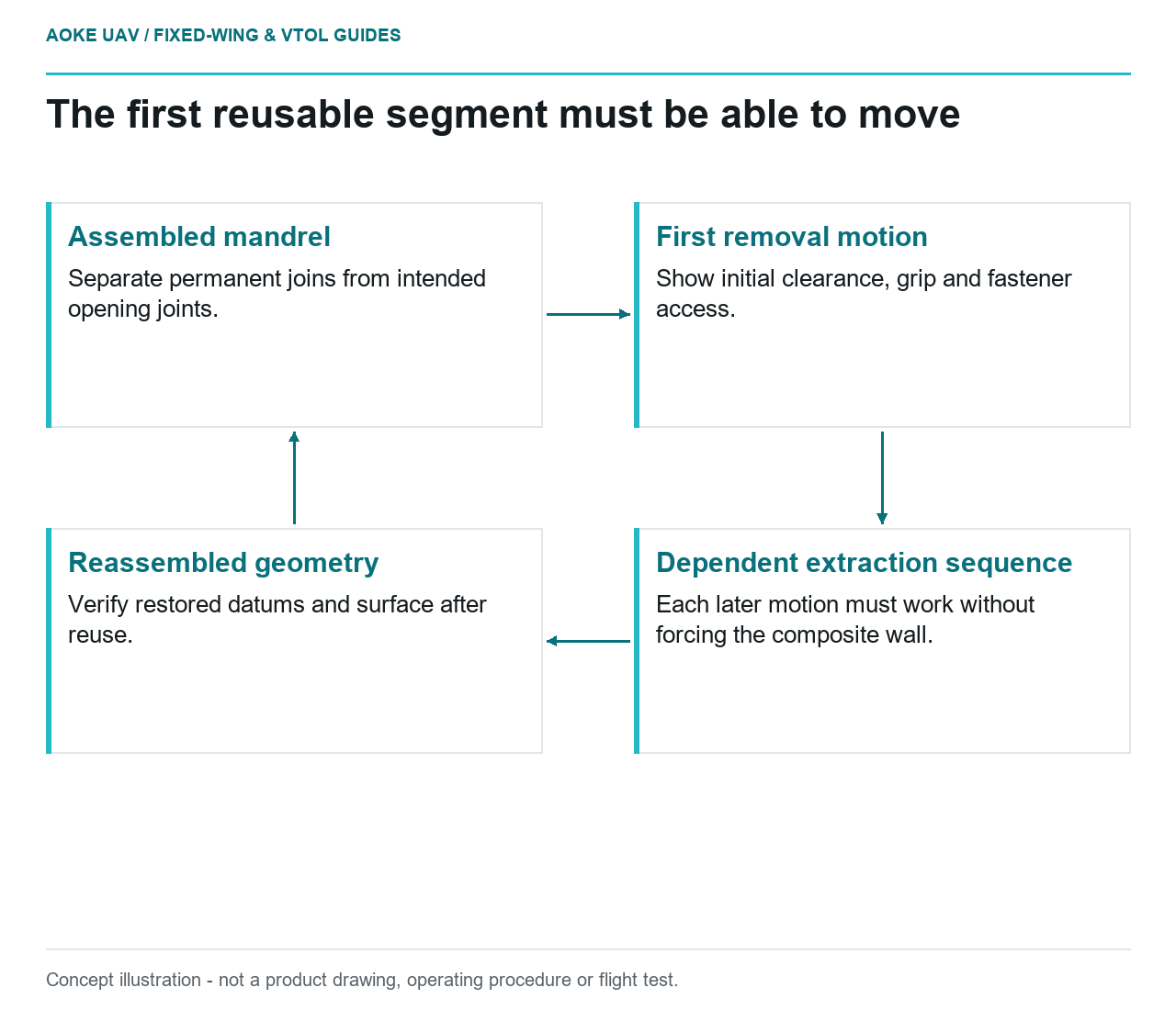
Read diagram notes
- Assembled mandrel: Separate permanent joins from intended opening joints.
- First removal motion: Show initial clearance, grip and fastener access.
- Dependent extraction sequence: Each later motion must work without forcing the composite wall.
- Reassembled geometry: Verify restored datums and surface after reuse.
An open end is an opportunity for tool removal, not proof that removal will work. Consider a hypothetical composite equipment duct for a large civil fixed-wing inspection aircraft. The duct has accessible ends but a shaped middle region. The manufacturing team proposes reusable printed mandrel segments rather than a disposable core. This is an editorial design review, not an GAUTEN production example or an instruction to force tooling out of a cured part.
Prove the extraction direction
Stratasys describes segmented tooling, alignment features and joined large tools. Its guide also discusses mandrel applications, but segmentation for printer capacity must not be mistaken for a demonstrated demountable extraction mechanism. [1]
In our duct study, give every segment an explicit removal direction and identify the space required to start that motion. A segment that can travel out after its neighbor is gone may still be impossible to move first. Model the sequence, including fastener access, grip locations and the support required for the composite part during release. Keep the proposed sequence attached to the design revision.
Review the complete interior, not only the largest cross section. A local return, internal shoulder or flange can invalidate an otherwise plausible straight withdrawal. The fixed-wing installation may favor a particular duct shape, but manufacturing access is a competing requirement to resolve openly. Do not make the thin composite wall the flexible element that compensates for a trapped tool.
Separate printable sections from reusable segments
The OEM’s segmentation discussion emphasizes alignment and mechanical joint geometry; it includes permanently joined examples. Those examples do not, by themselves, establish repeated disassembly performance. [1] Our proposed reusable tool therefore needs its own definition of which joints open, which remain permanent and how the pieces locate when assembled.
Put repeatable datums where they can be reached for measurement. Record the relationship between the external reference features and the molding surface. If a joint is adjusted by hand until it looks smooth, the assembly method remains underdefined. Define how segment identity, orientation and mating order are distinguished without relying on an operator’s memory.
For this large fixed-wing duct, the review should include the support stand as part of the tooling system. Reassembling identical segments on a different support arrangement is a changed condition to assess, not automatically an equivalent setup. Check that assembly hardware can be removed in the intended order without reaching through an inaccessible finished opening.
Review draft and trapped features together
Use a digital removal study to list potential interference, then plan a controlled physical demonstration. Neither step should be advertised as certification. We would assess release with a representative nonflight article before using the fixture on a production-intent laminate. The demonstration should show the sequence under the actual proposed support conditions, not just with loose segments on a bench.
Define a stop condition for unexpected resistance. Pulling harder is not an acceptable substitute for understanding interference. If an access restriction only becomes obvious after cure, record it as a design finding and revise the tool or part interface through the responsible engineering process. Any allowable release loads would require applicable evidence absent from this explainer.
Verify reassembly across uses
Reuse is a claim about repeated restoration of the working geometry. Our suggested checks would compare reference features, segment interfaces and the completed tool surface after disassembly and reassembly. Preserve the measurement arrangement so an apparent change can be distinguished from a changed inspection setup. Record repairs and replacements by segment rather than silently exchanging parts.
The decision between reusable and sacrificial tooling should include inspection effort, replacement logistics and extraction risk, not just print consumption. A reusable concept with uncertain alignment may be less defensible than a well-characterized disposable approach. Conversely, a proven extraction sequence may justify further reusable-tool development. The cited material is OEM process-specific tooling guidance, not material allowables, UAV flight approval or qualification of this hypothetical fixed-wing duct.