Concept illustration
Read diagram notes
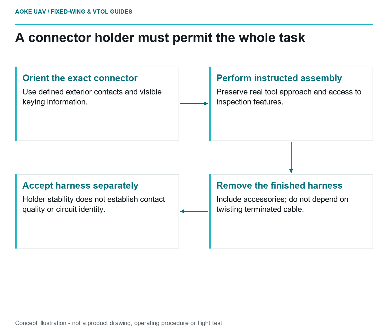
- Orient the exact connector: Use defined exterior contacts and visible keying information.
- Perform instructed assembly: Preserve real tool approach and access to inspection features.
- Remove the finished harness: Include accessories; do not depend on twisting terminated cable.
- Accept harness separately: Holder stability does not establish contact quality or circuit identity.
A connector holder can make an assembly task easier to perform without making the resulting harness correct. Consider a hypothetical off-aircraft workbench for payload harnesses serving a large civil fixed-wing mapping aircraft. A printed nest holds a camera-bay connector while an operator follows its actual assembly instructions. The aid is temporary ground tooling, not an installed wing connector, strain-relief design or electrical specification.
Specify holding and orientation only
Formlabs includes assembly aids within its tooling guidance and recommends checking printed tools dimensionally and functionally. Its article does not provide instructions for a particular electrical connector. [2]
For our fixed-wing payload harness, define which exterior surfaces the nest is permitted to contact and how connector orientation is shown. Use the exact connector identity and applicable OEM instructions as inputs. The fixture drawing should not create its own pin numbering, insertion depth or terminal preparation rules.
Make a reversed or incorrectly seated connector detectable during setup. A printed arrow can assist identification, but our proposed review would also check the actual connector key and the operator’s view of the work. Determine what the fixture can prevent physically and what still requires a procedural check. Do not claim mistake-proof assembly when a wrong configuration can still be loaded.
Preserve access to the actual assembly tools
Rehearse the connector supplier’s assembly sequence with a representative nonflight workpiece. Include the real tools and connector accessories intended for the operation. A holder that accepts the connector body may still block a tool approach or cover a feature that must be inspected before the next step.
In this scenario, cable support is reviewed separately from connector retention. Leave room for the specified strain-relief components and the relevant supplier-defined cable handling requirements. No generic cable bend radius, pull force or clamp torque is supplied here. Those values cannot be inferred from whether the printed nest seems comfortable to use.
Consider the order in which the completed harness will leave the aid. If removal requires twisting a terminated cable or pulling on a contact-bearing feature, revise the concept before accepting it. Evaluate removal with the completed connector accessories fitted, not only with an empty housing that is easy to lift out.
Control debris and material contact
Our proposed tooling inspection would look for damaged edges and loose material near the work zone before each defined use sequence. Specify the cleaning route appropriate to the selected print and assembly process. Do not invent a cleaning solvent or assume a coating is electrically suitable merely because it protects the fixture surface.
Keep mating and contact regions accessible for the inspection required by the actual connector instructions. Where the fixture hides a relevant area, change the holding arrangement or define an approved inspection stage before loading. A visually tidy bench is not the inspection record.
For sensitive electronics, obtain the applicable handling requirements rather than assuming an arbitrary print provides static protection. The purpose of this explainer is to identify that unanswered interface question, not to classify a material or prescribe an electrical safety arrangement without the relevant evidence.
Separate fixture acceptance from harness acceptance
We would maintain one record for the holder’s geometry, revision and functional trial, and another for the harness assembly and required electrical checks. The latter must follow the actual engineering and connector documentation. A connector remaining stationary in its nest says nothing by itself about circuit identity, contact quality or the completed harness’s required test results.
In the large fixed-wing camera-bay workflow, release the harness only through its separate inspection route, and remove the temporary aid before installation. Any later installed cable restraint is a different design item. The OEM tooling source supports general aid-development practices; it supplies neither connector ratings nor flight approval, and this hypothetical example claims no GAUTEN manufacturing result.