Concept illustration
Read diagram notes
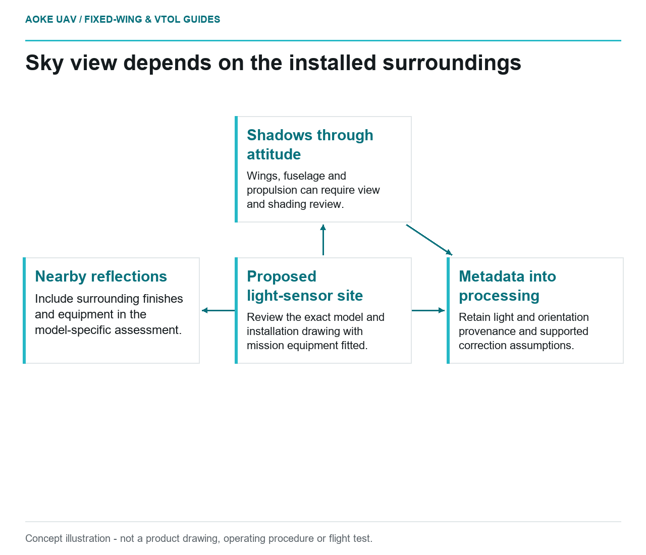
- Proposed light-sensor site: Review the exact model and installation drawing with mission equipment fitted.
- Shadows through attitude: Wings, fuselage and propulsion can require view and shading review.
- Nearby reflections: Include surrounding finishes and equipment in the model-specific assessment.
- Metadata into processing: Retain light and orientation provenance and supported correction assumptions.
A sky-facing sensor needs more than a convenient cable route. Imagine a hypothetical large fixed-wing aircraft carrying a multispectral camera over a civil land-monitoring area. Its long wings, upper-fuselage equipment and propeller installation leave several possible mounting locations for a downwelling light sensor. The integration question is which location satisfies the exact sensor’s requirements without creating an undocumented installation compromise.
Sky view and airframe shadowing
The November 2020 RedEdge-MX and DLS 2 Integration Guide instructs that particular DLS installation to avoid aircraft shadows and reflections, with clear sky view and a high fuselage location for fixed-wing use where possible. The source is an archived model-and-revision-specific example, not a general installation manual for every irradiance sensor or newer camera family. [2]
For the hypothetical aircraft, start with an installation drawing showing the proposed sensor view relative to the wing, fuselage, tail and propulsion components. Ask the responsible integrator to review possible shading through the intended acquisition attitudes and lighting directions. Do not declare the location satisfactory solely because the sensor sees open sky while the parked aircraft faces one direction.
If the selected sensor’s requirements cannot be met, record that as an integration issue to resolve with its supplier. Avoid improvising a mast height or moving aircraft hardware on the strength of a generic article. Structural, aerodynamic and operational acceptability remain separate aircraft-specific matters.
Attitude and orientation metadata
For the documented RedEdge-MX system, the guide says DLS 2 measures ambient light and sun angle and records information in image metadata for supported processing of lighting changes. It also describes orientation and stationary startup requirements for that unit. These details should be checked against the exact selected model and revision rather than transferred as universal procedures. [2]
In this fixed-wing integration review, identify which component supplies light, attitude, orientation and position information to the processing chain. Preserve the relevant metadata in original images and confirm that exports retain what the chosen software needs. If an alternative navigation source is used, ask how that changes metadata provenance. A field named attitude is not sufficient evidence that its reference convention matches the correction model.
Mounting and nearby reflections
The same model-specific guide warns about nearby bright or metallic finishes affecting light measurements and cautions against recessing the DLS 2 below its metallic base. These are substantive installation constraints for that documented unit, not justification to prescribe a coating, recess geometry or mechanical interface for another sensor. [2]
For the hypothetical large fixed-wing airframe, include surrounding finishes and nearby equipment in the installation review. Photograph the completed configuration with wings and normal mission equipment fitted, not just the bare fuselage on a bench. If a later modification changes the sensor’s surroundings, reopen the applicability review rather than assuming a working electrical connection proves an equivalent optical environment.
Follow model-specific integration requirements
The proposed evidence pack would identify the exact camera, light sensor, firmware, manual revision, installation drawing and processing configuration. Use the applicable manufacturer documentation for connectors, power and orientation. This article intentionally supplies no pinout or electrical setting: an installation example from one RedEdge model must not become wiring instructions for another payload.
Before the civil monitoring product is accepted, have the integration and processing teams agree on how illumination metadata will be checked and what conditions would make it unsuitable. In this scenario, review original image metadata and compare observations across acquisition segments rather than relying only on a successful startup indicator. Describe unresolved shadowing or orientation concerns in the handover.
A downwelling sensor is part of the measurement chain, not an automatic certificate of reflectance quality. The useful outcome is a documented, model-appropriate fixed-wing installation and a processing workflow whose assumptions remain visible. Where evidence is missing, restrict the claimed capability instead of replacing installation verification with the label sunlight corrected.
Related reading
- Antenna Placement Around Carbon Composite Airframes
- Payload Power Transients and Survey Sensor Integration