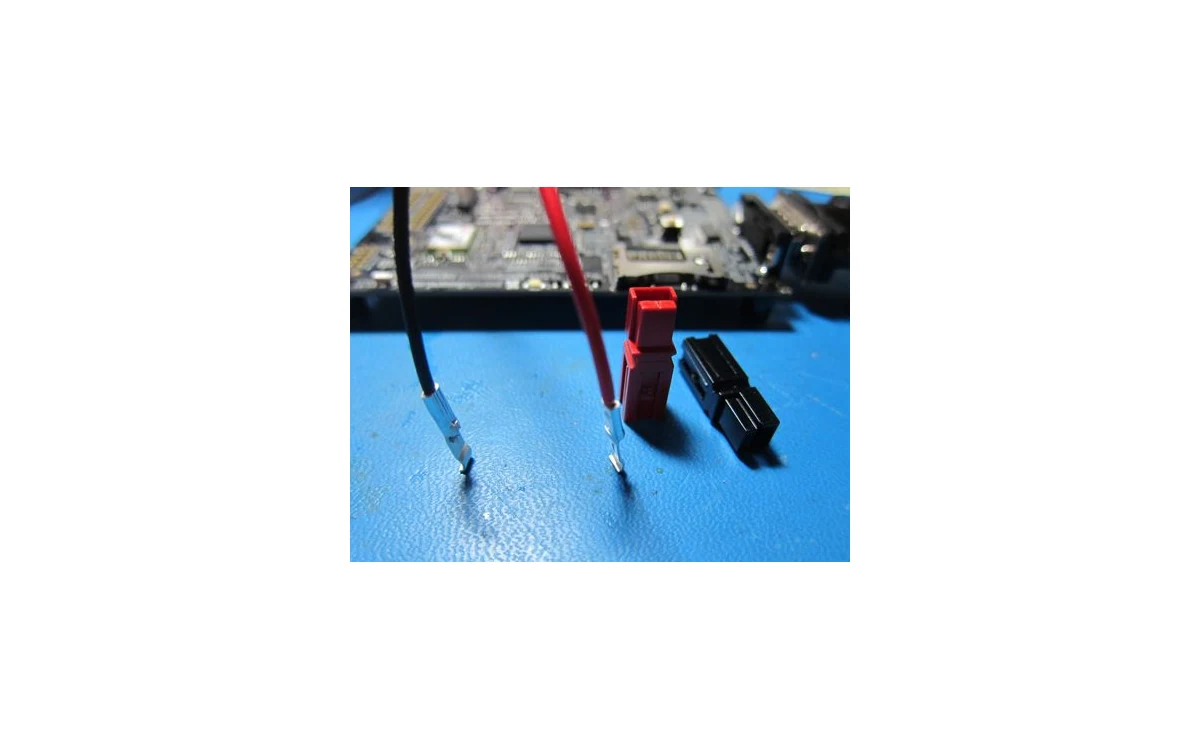
Consider a hypothetical large civil fixed-wing survey aircraft transported with its wings removed. Reassembly reconnects actuator power and, in a distributed-propulsion variant, a separate propulsion branch. A closed wing-root joint is not the same acceptance question as an electrically qualified connection. The bounded component example below uses Anderson Power SB® 50 documentation to explain that distinction. It is not an aircraft connector selection, an GAUTEN installation or a qualified installed rating.
Electrical and mechanical interface roles
The SB 50 datasheet identifies a genderless housing, contact-retention springs and different wire, PCB and busbar contact arrangements.[1] For our fixed-wing example, keep three interfaces distinct: wing structural attachment, mating between connector halves, and cable termination inside each half. Completing one does not establish the others. A wing fastener cannot serve as an electrical-engagement indicator merely because both connections disappear behind the same fairing.
The family name is not an installation rating. Anderson’s specification lists 120 A for its wire-to-wire UL 1977 configuration using the stated cable size, but 50 A for the wire-to-PCB configuration. Its rating basis includes cable temperature capability, recommended calibrated tooling and 25°C ambient; ratings are per position with all positions loaded. Separate temperature-rise and ambient-derating charts distinguish conductor configurations.[1]
Our conditional comparison holds the family name constant while changing the connection architecture. If a proposed wing interface changes from cable-to-cable to a PCB contact arrangement, the first rating cannot simply follow the housing into the new drawing. Even retaining cable-to-cable geometry does not establish equivalence if the enclosure temperature or conductor configuration differs from the documented basis. These are reasons to reassess the assembled interface, not instructions to operate either example at its catalog current.
Pin engagement and strain relief
Anderson’s assembly sheet separates terminating a contact onto its conductor from inserting that contact into the housing, where its tongue engages the retention spring. It specifies stranded copper for crimp contacts and recommended tooling, and prohibits assembly to live wires.[2] Contact retention inside one half is therefore distinct from engagement between two completed halves. Neither should be inferred from the wing reaching its structural stop.
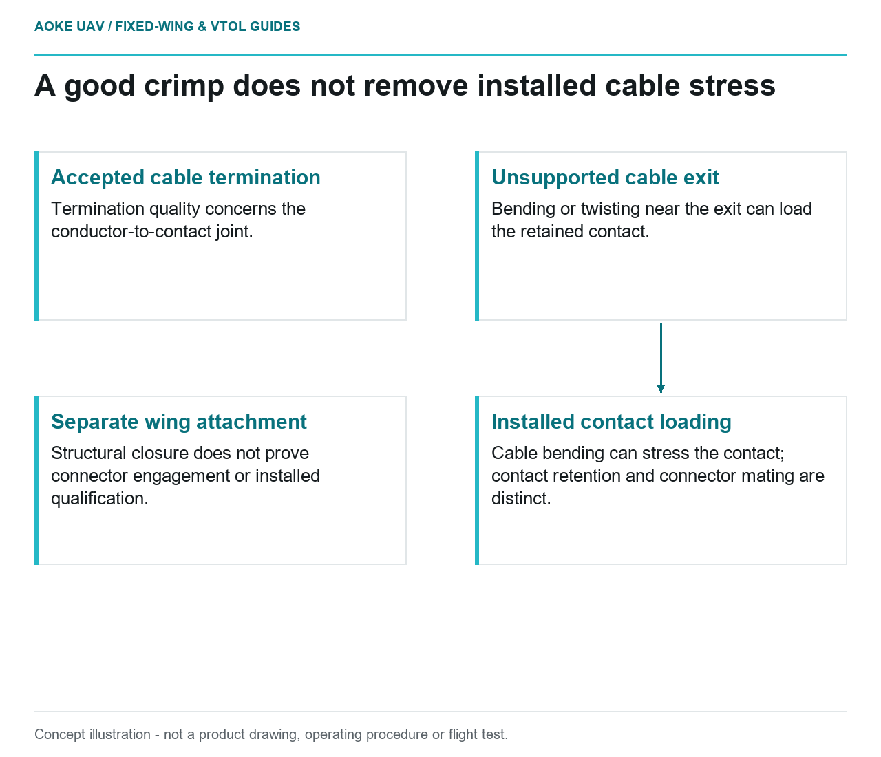
The separate PP75/SB50 crimp specification evaluates electrical resistance and wire pull-out alongside barrel fit and blade distortion. It explains that blade distortion can affect housing retention, resistance and mating forces. It also warns that a good crimp alone does not assure installed performance: wires bent or twisted near the exit can stress contacts, and should leave straight and be secured before bending or twisting.[3]
In our proposed integration comparison, harness A has an accepted termination but becomes taut as the wing closes; harness B retains the same termination with a separately assessed supported exit. The crimp result is unchanged, but the installed loading argument is not. This is why strain relief is not another name for a successful crimp or a retained contact. A routing rehearsal can expose the conflict; it cannot assign an acceptable force, bend radius or flight capability.
Assembly wear and inspection access
The SB50 specification distinguishes no-load mating cycles by plating: 10,000 for silver and 1,500 for tin. It lists hot-plug performance separately, with its own current, voltage and cycle conditions.[1] Those are different component test claims, not interchangeable service-life allowances. This article provides no energized-mating procedure.
For the hypothetical fixed-wing transport workflow, record which parts actually separate. Removing a wing is not automatically a connector mating cycle if a harness stays connected; replacing a contact also changes which item’s history is being tracked. Provide inspection access before closure so a retained contact, a damaged housing or a trapped cable can be assessed through the applicable maintenance process. Do not convert the catalog endurance figure into a field replacement interval or assume it covers contamination and handling damage.
Exact connector requirements and records
The practical conclusion is a conditional configuration argument: the same family can contain different contact architectures, termination acceptance criteria and endurance conditions. The example establishes why those distinctions matter, not which connector this aircraft should use. Its controlled interface drawing would connect exact housing, contacts, plating, conductor, tooling and restraint arrangement to the evidence actually applicable to that assembly. Aircraft-specific loads, environment and maintenance acceptance remain unresolved; no catalog headline qualifies the assembled wing interface.
Related reading
Sources
- [1] SB® 50 Connectors
- [2] SB® Connector Assembly Sheet
- [3] Crimp Specification for Powerpole® 75 & SB® 50 Contacts
Visual summary
Concept illustration
Read diagram notes
- Accepted cable termination: Termination quality concerns the conductor-to-contact joint.
- Unsupported cable exit: Bending or twisting near the exit can load the retained contact.
- Installed contact loading: Cable bending can stress the contact; contact retention and connector mating are distinct.
- Separate wing attachment: Structural closure does not prove connector engagement or installed qualification.