Concept illustration
Read diagram notes
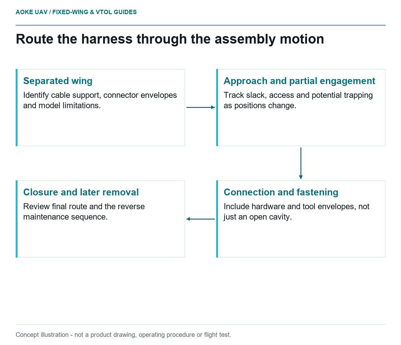
- Separated wing: Identify cable support, connector envelopes and model limitations.
- Approach and partial engagement: Track slack, access and potential trapping as positions change.
- Connection and fastening: Include hardware and tool envelopes, not just an open cavity.
- Closure and later removal: Review final route and the reverse maintenance sequence.
The final cable position is only one frame in a wing-assembly sequence. Consider a hypothetical large civil fixed-wing survey aircraft with removable wings for transport. A printed joint mockup is proposed to explore harness access before final airframe assembly. Its value is in exposing unresolved routing questions off-aircraft. It is not an installed harness acceptance test, an electrical rating assessment or an GAUTEN operational example.
Represent the assembly motion, not just the opening
Formlabs recommends inspecting printed manufacturing aids against CAD and testing their actual function. In this case, the proposed function is a routing rehearsal, so the model’s geometry and limitations must be explicit. [2]
Our fixed-wing mockup would identify the wing-root opening, adjacent structure, connector envelopes and the relative motion used to assemble the joint. Record which features are exact representations, simplified envelopes or placeholders. An omitted bracket should remain an open question, not quietly become available cable space.
Start the review with the wing separated. Move through approach, partial engagement, connection, fastening and final closure. At each stage, note where the cable is supported, where an operator can see it and whether access depends on a part that will later be installed. A route that looks clear after assembly may still be impossible to establish in the approved sequence.
Check access with the fasteners present
In the hypothetical trial, install representative hardware and use the intended tool envelopes. Check the space needed to reach fasteners while the connector and cable are in their relevant intermediate positions. Do not conclude that connector access is adequate from a mockup that leaves every nearby fastener and cover absent.
Ask whether disconnection remains possible during the intended maintenance or transport sequence. A routing concept should not quietly depend on pulling a cable to retrieve a connector from an inaccessible cavity. Where a retained access aid is proposed, treat it as another installation design item requiring its own evidence, not as an unreviewed extension of the temporary print.
Keep connector selection outside this article’s conclusion. The actual connector instructions and engineering requirements must supply mating, handling and electrical criteria. No cycle-life number, current rating or connection method can be established by a geometric routing mockup, even if the joint can be assembled repeatedly on the bench.
Identify strain-relief and pinch questions
Our review would trace the cable through all modeled positions and mark potential contact, tightening and trapping locations. Evaluate each finding against the relevant cable and connector supplier documents. Avoid selecting a universal bend radius from a generic printing guide or treating a flexible demonstration cord as representative of the production harness.
If a surrogate cable is used, record its differences and limit the conclusion accordingly. A route passing with a thinner, more flexible stand-in is an unresolved result until checked with appropriate representation. The same applies to a connector printed without a backshell or a strain-relief assembly that remains unspecified.
For the detachable fixed-wing interface, separate deliberate movement accommodation from uncontrolled slack. The mockup can help locate where slack would go during assembly, but our recommended output is a documented routing proposal, not a claim that an arbitrary loop is suitable for flight. Installed restraint and environmental behavior need their own substantiation.
Transfer the findings into controlled information
Photographs of a successful rehearsal are useful only when tied to a known configuration. Our proposed report would identify mockup revision, represented components, surrogate limitations, assembly order and observed conflicts. Locate findings on the engineering drawing and identify who must resolve each one.
Update the controlled route and work instructions through the responsible design process, then determine what installed-harness inspection remains necessary. The printed aid should retire or change identity when its geometry no longer represents the design. For the large fixed-wing survey aircraft, the outcome is reduced integration uncertainty, not proof of installed harness reliability, airworthiness or civil mission readiness.