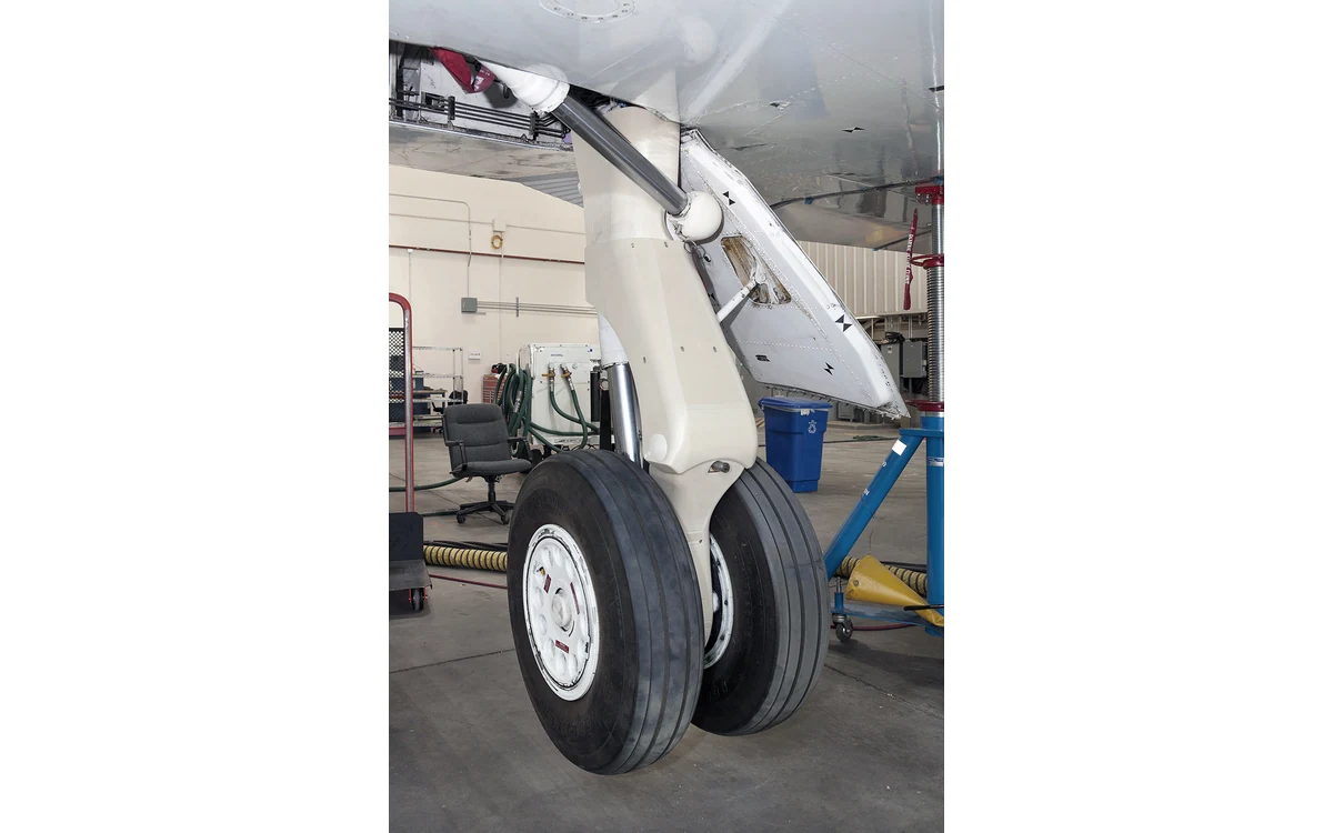
A payload fairing can look finished long before its engineering questions are settled. Consider a hypothetical printed shell around an antenna installation on a large civil fixed-wing survey aircraft. The shell stays on the ground. Its purpose is to make an integration review tangible: expose where people, connectors, covers, and adjacent assemblies need space, without implying that a production fairing is ready to fly.
Envelope and attachment access
Define the mockup as an envelope and access artifact. Identify the represented antenna revision, attachment locations, surrounding airframe definition, and features omitted from the model. A review can then record whether a specified connector can be inserted or a planned fastener reached in that represented arrangement. It should not record a broad statement that the installation fits every aircraft or every payload variant.
Formlabs recommends inspecting printed manufacturing aids against the CAD model and checking functional performance, including seating against locating surfaces. Applied cautiously to this mockup, that guidance supports verifying the artifact before trusting an interference observation. It does not establish the aircraft attachment design or validate the dimensional fidelity of a supplier model that has never been checked. [4]
Cooling and antenna interface questions
Use the shell to identify evidence requests rather than to simulate unrepresented behavior. Ask the thermal reviewer which openings, heat sources, operating states, and surrounding structures belong in the eventual cooling assessment. Ask the RF reviewer what material, coating, geometry, installation, and antenna data are required. Without that information, the visual absence of interference says nothing conclusive about cooling or antenna performance.
For this fixed-wing scenario, give each observation a limited statement: the represented cable route is accessible with the ground mockup in place, or the planned inspection opening needs review. Avoid upgrading those observations into claims about radiated performance or heat rejection. A transparent list of unresolved interfaces is a more useful design-review output than an attractive shell described as fully validated.
Surface finish and aerodynamic unknowns
A reviewer should also distinguish the printed surface from the intended production surface. Record where support removal, sanding, seams, or intentionally simplified contours affect the mockup. Formlabs advises minimizing supports on functional SLA surfaces and following material-specific post-processing instructions. Those are manufacturing-aid considerations, not aerodynamic evidence for the printed fairing or the later production part. [4]
If the design team wishes to claim reduced drag, it must define an appropriate aerodynamic comparison and obtain evidence for the installed configuration. This article supplies no such result. A large fixed-wing airframe review can still use the mockup to ask whether panel removal or maintenance access conflicts with the proposed contour, provided that the review does not confuse geometric discussion with measured aircraft performance.
Separate fit review from flight release
Keep a ground-only identifier on the artifact and in the review record. Record its CAD revision, inspected dimensions, physical limitations, and custody after the meeting. The following is a proposed workflow: resolve envelope issues, update the controlled installation definition, and route production-material, attachment, environmental, and aircraft verification questions to their responsible reviewers. Do not allow the review artifact to become retained hardware by convenience.
NASA-STD-6030 separates material/process control and part-production definition within its spaceflight framework. That is contextual support for keeping manufacturing identity and intended use explicit; it is not UAV approval. [5] For this hypothetical fixed-wing project, a completed mockup review closes only the questions actually represented and examined. Unresolved RF, thermal, aerodynamic, retention, and release evidence remains open on its own terms.
Related reading
- Nonstructural Radomes: Separate RF and Mechanical Requirements
- Cooling a Fixed-Wing Propulsion Bay: Evidence Before Ducts
Sources
- [4] Jigs, fixtures, and manufacturing aids
- [5] NASA-STD-6030: Additive Manufacturing Requirements for Spaceflight Systems
Visual summary
Concept illustration
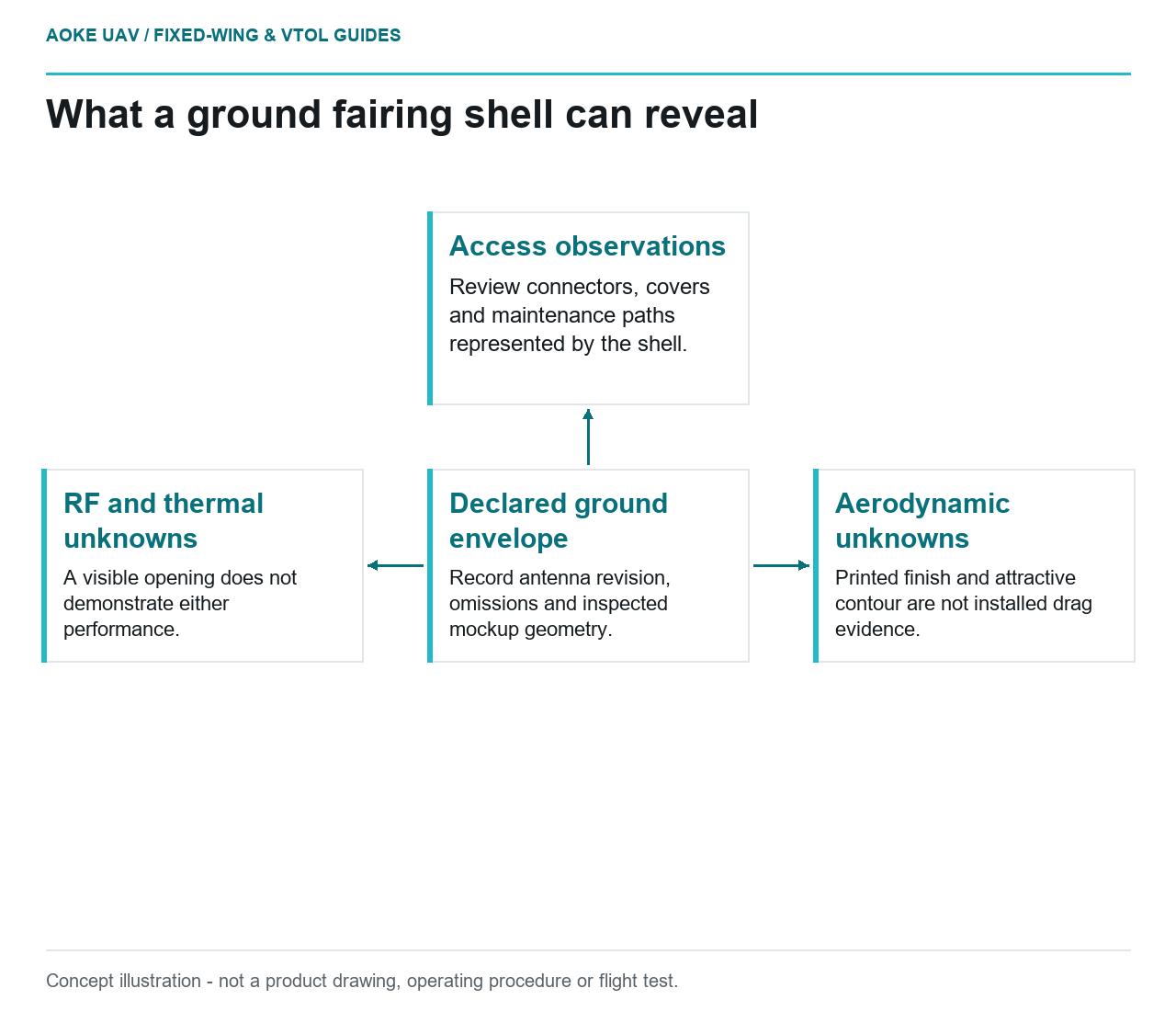
Read diagram notes
- Declared ground envelope: Record antenna revision, omissions and inspected mockup geometry.
- Access observations: Review connectors, covers and maintenance paths represented by the shell.
- RF and thermal unknowns: A visible opening does not demonstrate either performance.
- Aerodynamic unknowns: Printed finish and attractive contour are not installed drag evidence.