Concept illustration
Read diagram notes
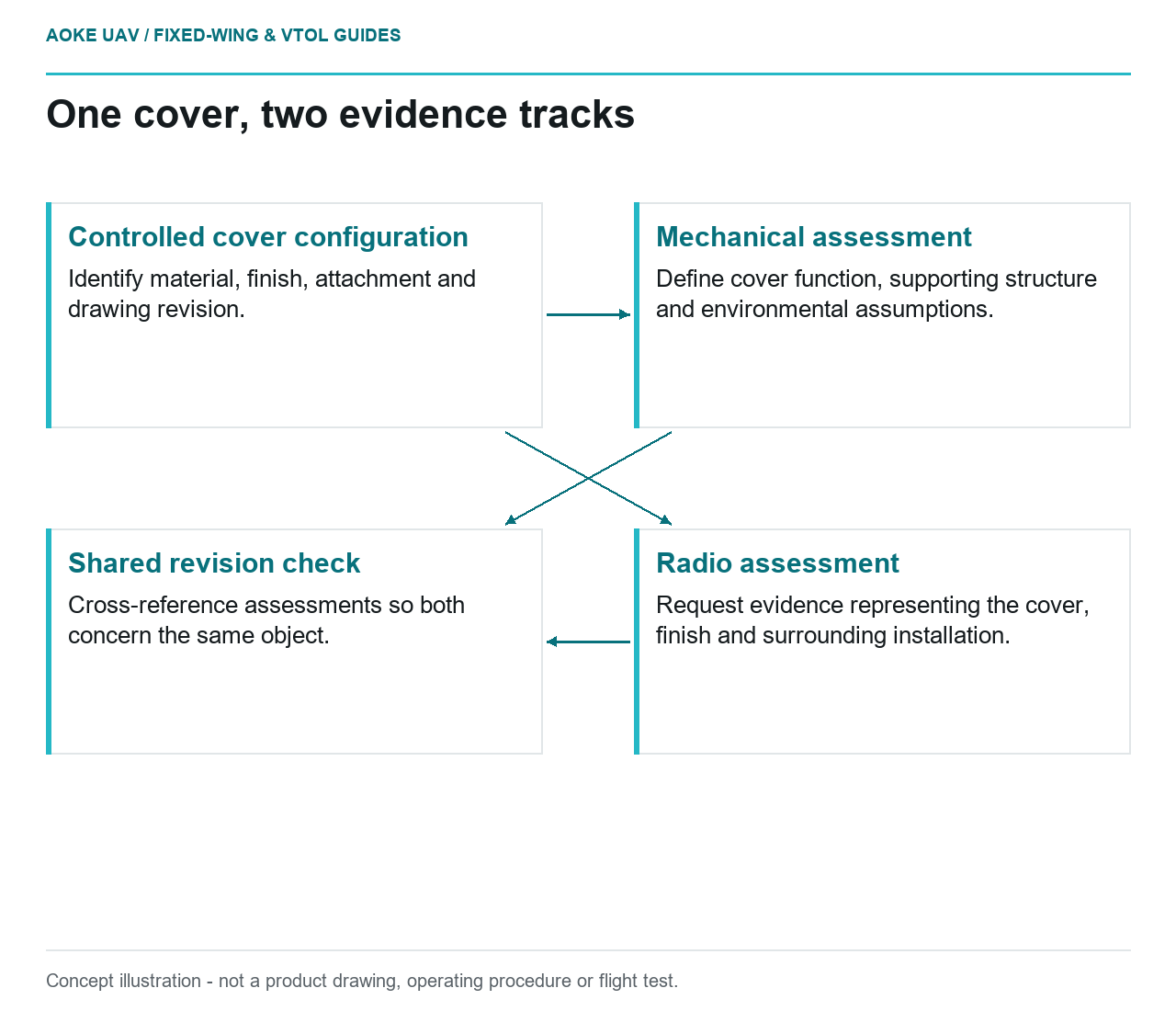
- Controlled cover configuration: Identify material, finish, attachment and drawing revision.
- Mechanical assessment: Define cover function, supporting structure and environmental assumptions.
- Radio assessment: Request evidence representing the cover, finish and surrounding installation.
- Shared revision check: Cross-reference assessments so both concern the same object.
A hypothetical large fixed-wing mapping project proposes a small cover over a navigation antenna. The proposal calls it a nonstructural radome and describes the material as radio-transparent. Those labels leave two different questions unanswered: what mechanical role the installed cover has and what radio evidence supports the exact assembly. No supplier transmission data is available in the offline source pack. The useful outcome is therefore a bounded review of evidence requirements, not a recommendation of a fiber, resin, coating or printed polymer.
Define whether the cover carries loads
Ask the designer to define nonstructural in the installation drawing. Does the cover merely enclose equipment, or does its attachment also retain a cable, constrain an antenna bracket or bridge an opening? Identify the aircraft structure supporting it and the interfaces that remain when it is removed. The label should describe an assessed function, not excuse missing documentation.
FAA composite guidance defines critical structure through its importance to overall flight safety and discusses configuration-specific structural details. Its US certificated-aircraft context does not classify this UAV cover, but it helps frame the question for the responsible design authority. [1] For the fixed-wing team, keep the cover’s classification separate from the consequences of a loose attachment or an undocumented change to the supporting shell.
Material and finish affect the interface
Describe the complete proposed cover: reinforcement, matrix, thickness definition, finish, adhesive, fasteners and any embedded features. These are requested configuration attributes, not prescribed construction details. Ask the antenna supplier which attributes its installation assessment needs and ask the cover supplier which configuration its own material information actually represents.
Without measured or otherwise applicable radio evidence, do not call the assembled cover transparent at any frequency. A material family name cannot supply the missing test configuration. In the hypothetical fixed-wing review, an unpainted sample and a finished cover should be treated as distinct evidence descriptions until the supplier establishes their relationship. No attenuation figure or comparison is justified here. The gap is specific: installed radio behaviour remains unverified, rather than being silently inferred from a mechanical datasheet.
Attachment and environmental exposure
The attachment review should identify the mounting location, retention arrangement, access and environmental assumptions. Ask whether removal can be accomplished using the applicable aircraft maintenance instructions and whether the supporting region can be inspected afterward. Avoid specifying bolt torque, adhesive preparation, cover-wall dimensions or retention loads from generic examples.
FAA guidance identifies environmental exposures and protective surface layers as structural considerations, and it ties bonding to qualified processes rather than appearance. [1] Use those principles to request evidence for the particular installation. For this large industrial fixed-wing scenario, the design authority should also identify which cover changes require reassessment. A supplier statement about bare material does not automatically cover a later coating, different attachment or revised opening in the airframe.
Separate RF testing from structural approval
Keep two evidence tracks in the review record. One should address the mechanically installed cover and its effect on the airframe. The other should address radio performance with the relevant cover, finish and surrounding installation represented. Cross-reference them through the same drawing revision so that neither assessment concerns a different object.
The FAA’s building-block discussion explains why material-level results need a justified connection to more complex structural details and components. It does not validate radome transmission or turn a tooling guide into flight-cover qualification. [1] Here, a tooling design source was deliberately not used as RF evidence. Before the hypothetical fixed-wing program accepts the proposal, its record should identify missing supplier data and the responsible reviewer. Passing a fit check answers whether the cover fits; it does not establish either radio suitability or structural acceptance.
Related reading
- Antenna Placement Around Carbon Composite Airframes
- Printed Fairing Prototypes for Fixed-Wing Integration Reviews