A camera supplier offers a printable model so an integrator can review a crowded payload bay. That is potentially useful only if both parties understand what the file represents. In this hypothetical large civil fixed-wing mapping project, the request is for a ground fit-test artifact, not a production camera drawing or a flight-qualified substitute. Its declared fidelity determines which integration questions it can help answer.
Model fidelity and excluded features
Ask for the exact sensor model and revision represented, the intended scale and units, and a list of simplifications. Identify whether the exterior shape, fastening features, connectors, cooling openings, or service covers are omitted or approximate. Request a clear distinction between supplier-controlled interface data and geometry supplied only for visualization. Do not assume a detailed-looking mesh has production-drawing authority.
Formlabs recommends inspecting printed manufacturing aids against the original CAD model and checking their functional performance. [4] That supports verifying the physical artifact against its declared source. It cannot establish that a simplified supplier model accurately represents the real camera. The procurement request should therefore ask the supplier to define the model’s intended use and the information it is not authorized to convey.
Mounting datums and connectors
Specify which mounting interfaces and reference datums are needed for the planned review. Ask which dimensions or tolerances must come from separate controlled documentation. For connectors, request the represented configuration and any relevant mating-envelope information from the supplier rather than inventing a generic clearance. A printed socket shape alone should not be taken as an electrical connector specification or an installation instruction.
For this fixed-wing bay scenario, organize the request around actual decisions: can the defined mounting interface be approached, can a represented mating connector be installed, and can the planned service cover be removed? Record the model limitations alongside each question. An artifact that only captures the outer bounding shape may still be valuable, but it should not be used to close an unrepresented attachment or connector-access issue.
Clearance and cable representation
Identify which cables, mating plugs, nearby equipment, and removal paths belong in the physical review. If the team prints simplified stand-ins for those items, label the simplifications and keep their source definitions traceable. Do not prescribe bend radii or installation clearances without the applicable component instructions. The review can reveal a question even when it cannot yet provide a validated answer.
Formlabs’ advice to examine seating at locating surfaces and supports provides a useful functional-check concept. [4] Apply it by confirming that the artifact sits in the intended reference arrangement before interpreting an interference. Keep print finishing and measurement differences visible. If the model requires unrecorded sanding to fit, the team should resolve whether it changed the artifact or revealed a problem in the represented installation.
Record what the artifact cannot validate
State that the printed stand-in does not represent camera mass properties, heat generation, optical performance, RF behavior, or environmental capability unless separately defined and evidenced. Those exclusions prevent a convenient physical model from being mistaken for a complete integration test article. The source used here supplies manufacturing-aid guidance, not camera-specific verification results, mounting loads, or aircraft performance evidence.
The final request and returned artifact record should include supplier revision, intended review questions, known omissions, local print identity, inspection results, and unresolved interfaces. For a large fixed-wing program, this turns a helpful model into an auditable communication tool. It does not make the geometry authoritative beyond its declared scope, and it leaves the actual sensor installation and aircraft release to their applicable engineering processes.
Related reading
- Printed Payload Mockups Before Cutting an Airframe
- A Payload Bay Checklist for Fixed-Wing Survey Sensors
Sources
Visual summary
Concept illustration
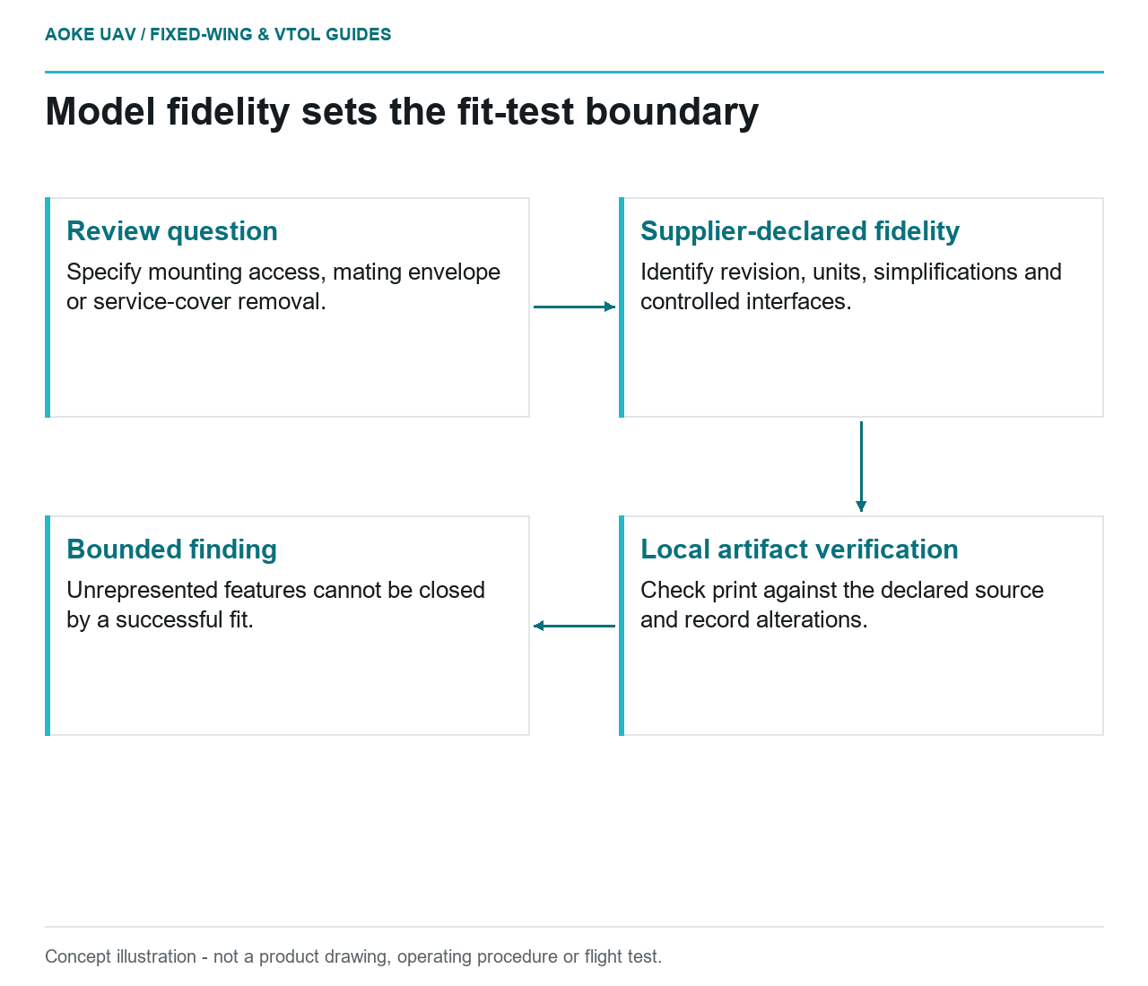
Read diagram notes
- Review question: Specify mounting access, mating envelope or service-cover removal.
- Supplier-declared fidelity: Identify revision, units, simplifications and controlled interfaces.
- Local artifact verification: Check print against the declared source and record alterations.
- Bounded finding: Unrepresented features cannot be closed by a successful fit.