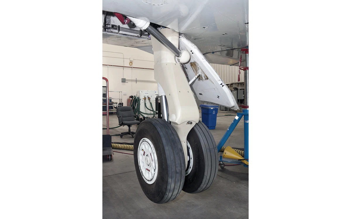
The cheapest useful payload model may deliberately do very little. Imagine a large industrial fixed-wing mapping aircraft whose belly bay is being evaluated for a camera installation. A printed geometric mockup is proposed before anyone cuts an airframe panel. The intended deliverable is an access and interface review, not a flight installation. This is a hypothetical editorial scenario and does not describe an GAUTEN aircraft, customer or tested payload combination.
State the model’s fidelity before use
Formlabs recommends dimensional inspection against the originating CAD model and functional testing of printed manufacturing aids. Those checks address the aid itself; they do not make an envelope model representative of an operational sensor. [2]
For our fixed-wing bay, label the mockup as geometry-only and list what its geometry includes. Identify the source and revision of the camera envelope, mounting interface and connector positions. If a connector shell or removable cover has been simplified, mark that omission before a reviewer draws a conclusion from the model.
Keep a fidelity register with three categories: represented, deliberately omitted and unknown. A missing heat sink is not the same as a simplified cosmetic surface when reviewing access. If the available sensor information does not define an important feature, record the uncertainty rather than inventing a plausible printed substitute.
Check the complete access sequence
In this scenario, begin outside the aircraft. Can the proposed payload enter the opening, reach its mounting position and later leave without unauthorized disassembly? Model the path through the bay as well as the parked envelope. Include the bay cover and neighboring equipment in the review, not only an empty fuselage cavity.
Then assess access to fasteners and connectors with the mockup in place. Represent the required tool approach and the cable-end assembly rather than only a connector outline. Where a camera or mount moves, review the full intended motion using applicable sensor and installation documentation. The mockup does not establish permissible cable bending or articulation limits.
Record clashes as located findings tied to the bay drawing. The recommendation is not to trim the aircraft until the print fits. First decide whether a finding arises from uncertain source geometry, a mockup error, an assembly-sequence issue or an actual proposed installation conflict. Each calls for a different corrective action.
Keep mass representation separate
A lightweight print is useful precisely because it can isolate geometry. Do not casually describe it as a payload simulator. In our fixed-wing example, it has no demonstrated relationship to payload mass distribution, mounting loads or the complete aircraft balance condition. Those questions remain open even when every geometric check passes.
If a later test needs representative mass, define a separate controlled article and test objective. Record how mass and its distribution would be established, which supports are approved for that test and what evidence is required before handling the assembly. This explainer provides no ballast arrangement or structural loading prescription.
Preserve the geometry-only model as a distinct configuration. Adding loose weight to the same print and keeping the original label would blur two different tools with different evidence needs. A useful early mockup should reduce uncertainty, not make the boundaries of the next test harder to recognize.
Publish the unresolved integration questions
Our suggested report would include the mockup revision, measurement check, assembly sequence, access findings and a list of unresolved issues. Keep structural substantiation, heat rejection, electrical compatibility, vibration and sensor calibration outside the fit-check conclusion unless each has its own applicable evidence.
For a large fixed-wing aircraft intended for civil mapping, a successful fit check is permission to advance the design review, not to launch a mission. Resolve any proposed airframe modification through the responsible design process using real installation data. The cited OEM source supplies general manufacturing-aid practices; it does not approve this camera installation or demonstrate mapping performance.
Related reading
- Removable Payload Trays Without Hidden Structural Assumptions
- A Payload Bay Checklist for Fixed-Wing Survey Sensors
Sources
Visual summary
Concept illustration
Read diagram notes
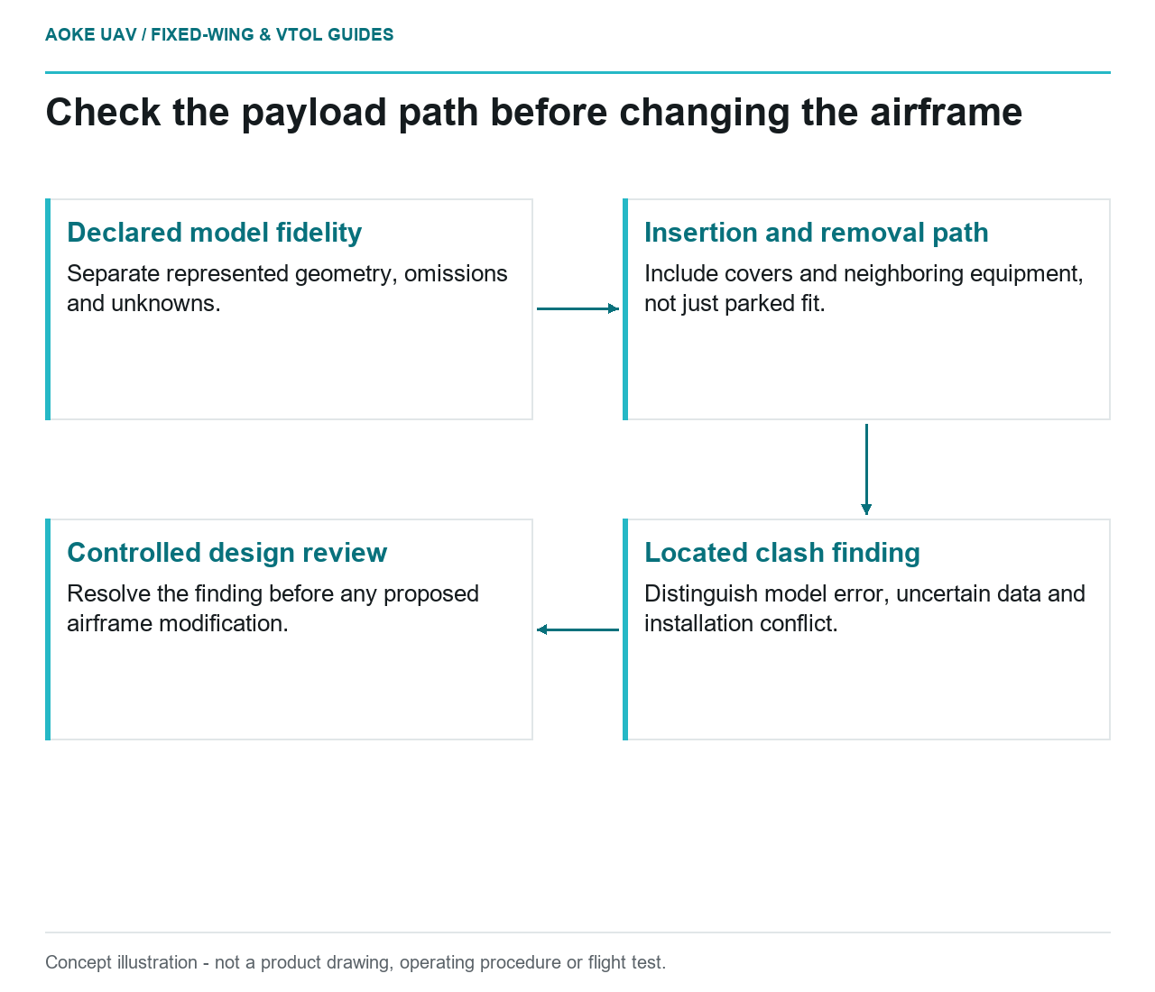
- Declared model fidelity: Separate represented geometry, omissions and unknowns.
- Insertion and removal path: Include covers and neighboring equipment, not just parked fit.
- Located clash finding: Distinguish model error, uncertain data and installation conflict.
- Controlled design review: Resolve the finding before any proposed airframe modification.