Concept illustration
Read diagram notes
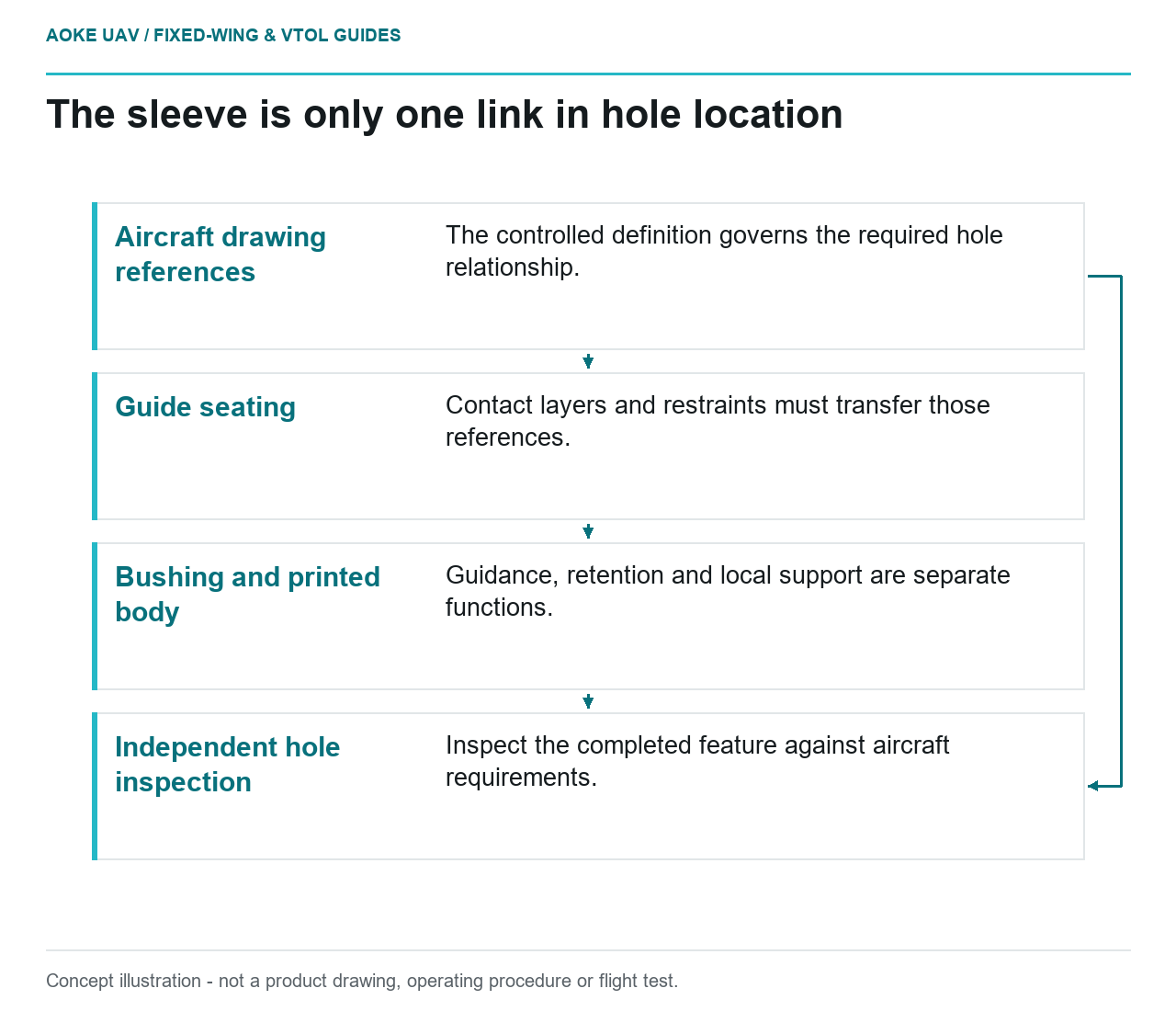
- Aircraft drawing references: The controlled definition governs the required hole relationship.
- Guide seating: Contact layers and restraints must transfer those references.
- Bushing and printed body: Guidance, retention and local support are separate functions.
- Independent hole inspection: Inspect the completed feature against aircraft requirements.
Suppose a workshop proposes a bushing-supported printed drilling guide at the detachable wing interface of a large fixed-wing survey aircraft. The useful question is not whether a printer can make the shape. It is whether this aid can locate and support the approved operation without becoming the authority for accepting the resulting hole. This is a hypothetical editorial review, not an GAUTEN manufacturing procedure or structural drilling specification.
Drawing requirements versus jig geometry
Write the hole’s required relationship to the aircraft’s controlled references before designing the guide. In this scenario, the drawing and approved manufacturing data would govern location, size and inspection. The tool designer would then identify how the guide transfers those references. No hole dimensions, edge distances or cutting settings can be inferred from this general article.
Stratasys includes drill guides among ancillary FDM tooling and describes incorporating bushings and inserts. It also notes that printed horizontal holes can have poor resolution and discusses secondary finishing for tool features. This supports examining the guide’s manufactured interfaces, not accepting a structural aircraft hole directly from the print model. [1]
For the fixed-wing project, compare the guide tolerance chain with the required aircraft result. Ask which interfaces are measured, which are adjustable and which can move during use. If the tool’s ability to locate the operation is unsubstantiated, a printed guide should remain a development proposal rather than be issued to production.
Bushings and local wear
Formlabs recommends metal or hybrid approaches for very high-wear regions and warns against unsupported thin features unless validated. Stratasys discusses local reinforcement around inserts and bushings. Together these sources support considering a hybrid tool, but neither supplies an approved bushing fit for this wing joint. [2] [1]
In the hypothetical review, separate the bushing’s internal guidance function from its retention in the printed body and the body’s seating on the aircraft. A metal sleeve does not answer all three questions. Record how installation and subsequent inspection will establish its position, condition and stability.
Develop wear and damage checks for the actual tool duty. The project should decide who may replace a bushing and what must be remeasured afterwards. Do not assign a universal replacement interval or assume a catalogue bushing makes the surrounding printed structure suitable. Supplier installation instructions and the real tooling design are still missing inputs.
Chip clearance and surface protection
For this large fixed-wing assembly, use a physical access review to ask where process debris could collect, whether the tool obscures the working area and how the guide can be removed without dragging across a finished surface. These are proposed planning questions, not a claim about a tested chip-control design.
Formlabs calls for functional checks of workpiece seating and support, and for clamping requirements to reflect the operation’s forces and machine conditions. That is a reason to substantiate the fixture under its actual use, not to publish generic clamp forces or feeds and speeds for an unknown composite joint. [2]
Keep surface protection compatible with the datum scheme: an unrecorded soft pad should not silently become the locating reference. The responsible engineer should define any contact layer and inspect the tool in that configuration. Debris management and worker protection belong in the approved shop procedure, not in assumptions left to the person holding the guide.
Hole inspection independent of the guide
Specify how the completed feature will be inspected without treating the guide’s continued fit as proof of acceptance. The proposed inspection must address the drawing requirements and any applicable material-specific damage criteria. Those criteria are aircraft-specific and are not supplied by the retrieved additive-tooling sources.
The hypothetical handoff would include the guide identity, drawing revision, bushing installation record, pre-use condition and references to approved drilling and inspection instructions. Record a tool anomaly separately from the hole disposition. An apparently acceptable hole does not automatically return a suspect tool to service.
The decision boundary is clear: a printed guide may assist a controlled process only when its own suitability is established. It cannot replace the engineering definition of a structural fastener hole, nor can successful seating of wing hardware establish the strength of the completed fixed-wing joint.