Concept illustration
Read diagram notes
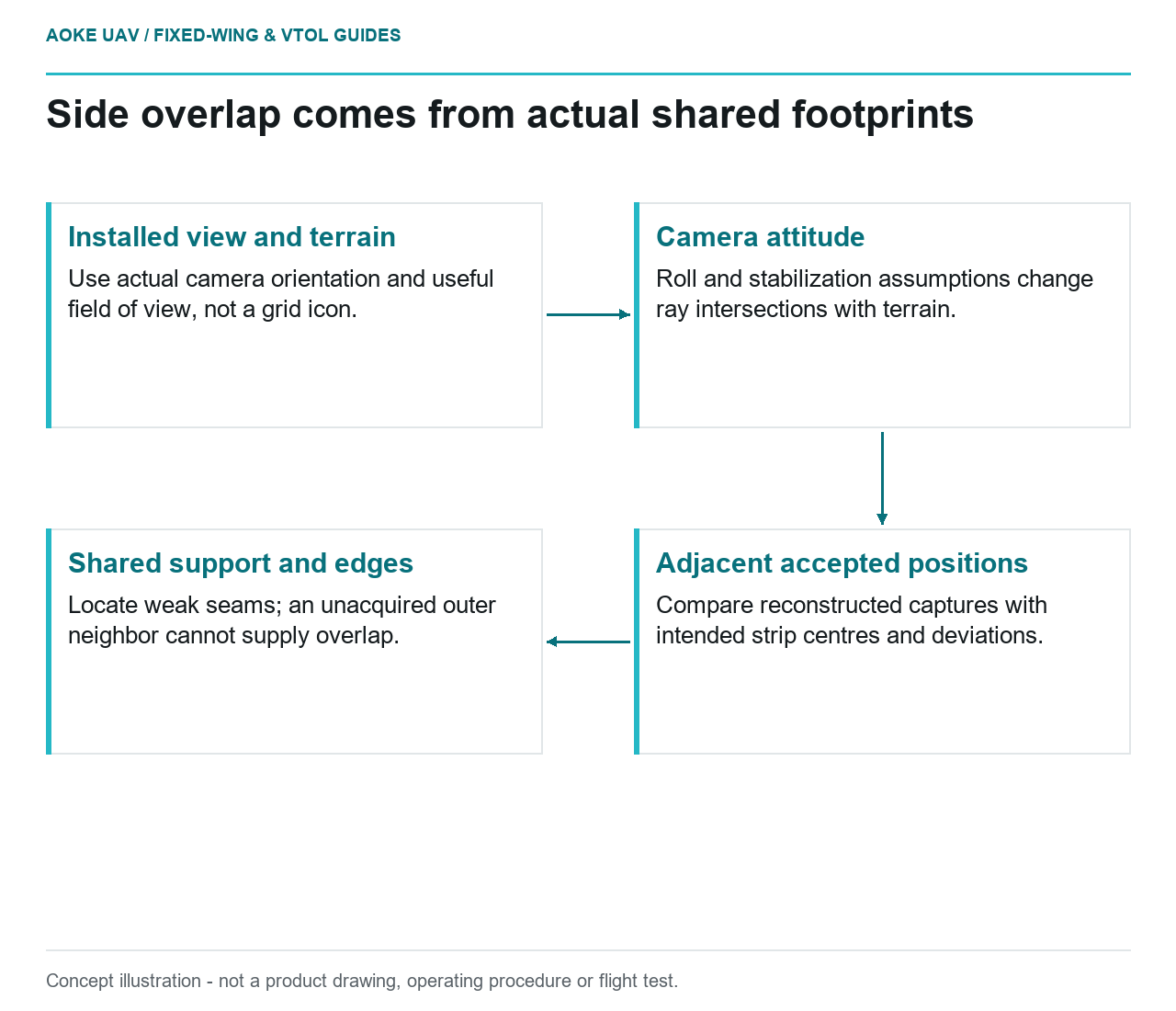
- Installed view and terrain: Use actual camera orientation and useful field of view, not a grid icon.
- Camera attitude: Roll and stabilization assumptions change ray intersections with terrain.
- Adjacent accepted positions: Compare reconstructed captures with intended strip centres and deviations.
- Shared support and edges: Locate weak seams; an unacquired outer neighbor cannot supply overlap.
Footprint width and terrain
A hypothetical large industrial fixed-wing survey uses adjacent strips to map a broad civil development area. The planner displays a tidy grid, yet the integration review must ask which ground is actually shared by usable images from neighbouring strips. This article focuses on area-grid side overlap, not the visibility envelope of a narrow infrastructure corridor. Treat the footprint discussion as a simplified geometric planning model that still requires verification against the installed system.
Begin by identifying the camera’s orientation and useful field of view. The RedEdge-MX Revision 04 guide specifically tells users to swap horizontal and vertical mission-planner parameters if the camera is mounted in portrait rather than landscape orientation. [3] The transferable lesson is to check the actual installation. Its dimensions and instructions are not specifications for another camera, and a correctly entered nominal footprint is only the start of the coverage review.
Roll changes the useful footprint
In the hypothetical geometric model, tilting a downward-looking camera changes where its image rays intersect the terrain. Therefore, ask how aircraft roll and any payload stabilisation are represented when assessing side overlap. Do not equate the grid’s nominal footprint with the accepted footprint throughout a flight. Specify what attitude records are available, what reference frame they use and whether they describe the camera or only the navigation unit.
The RedEdge-MX guide asks that the camera maintain a clear view below the aircraft and discusses keeping it directed downward; its automatic overlap mode explicitly does not account for side overlap. [3] This illustrates why a forward-triggering feature cannot be used as evidence of inter-strip support. For the large fixed-wing scenario, request an assessment of the proposed mounting arrangement and camera attitude rather than assuming a stabilised optical axis from the aircraft label.
Track deviation and edge geometry
Next, distinguish intended strip centres from reconstructed acquisition positions. In our review method, examine adjacent accepted image sets over the terrain, not only the commanded routes. Ask whether useful shared coverage remains where strip position, orientation or local height differs from the nominal assumptions. Keep the outer project boundary as a separate case because the proposed plan cannot rely on a neighbouring strip that was never acquired outside that boundary.
Do not choose a universal side-overlap percentage as the conclusion. Instead, ask the survey specialist to justify the project’s image-support requirement and the integrator to show that the proposed configuration can satisfy it. Where the analysis is uncertain, document whether a revised strip arrangement, a qualified delivery area or additional acquisition evidence is needed. Leave flight-path feasibility, airspace access and aircraft limits to their separate applicable reviews; a footprint diagram grants none of those permissions.
Coverage review from actual image positions
USGS describes acquisition geometry, camera calibration and tie-point distribution as interconnected, and calls for tie points distributed horizontally and vertically. [1] For this hypothetical fixed-wing block, retain an image-support review that makes weak inter-strip areas visible. Include which captures were accepted, the assumptions used to project their useful footprints and where terrain information was insufficient. A processed mosaic should not be the only record used to resolve those questions.
Finish with a coverage decision that distinguishes observed image support from expected product quality. Mark unresolved edges or seams, assign their review to a named project role and preserve the relevant source-image identifiers. If reacquisition is considered, identify the precise deficient region rather than reflexively repeating the whole grid. This produces an auditable question about the actual large-aircraft payload and acquisition geometry, without inventing flight results, terrain clearance or achieved positional accuracy.
A practical coverage exhibit for this scenario would overlay the requested area, intended strip centres and the useful footprints reconstructed from accepted captures. Use a separate annotation for assumptions about camera attitude and terrain. The reviewer should be able to point to a weak seam and identify the contributing image pair or missing support, rather than merely reading a nominal overlap percentage. Such an exhibit remains an acquisition assessment, not an independent positional-accuracy test.