Concept illustration
Read diagram notes
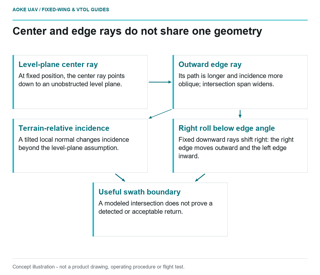
- Level-plane center ray: At fixed position, the center ray points down to an unobstructed level plane.
- Outward edge ray: Its path is longer and incidence more oblique; intersection span widens.
- Right roll below edge angle: Fixed downward rays shift right: the right edge moves outward and the left edge inward.
- Terrain-relative incidence: A tilted local normal changes incidence beyond the level-plane assumption.
- Useful swath boundary: A modeled intersection does not prove a detected or acceptable return.
A hypothetical large industrial fixed-wing civil survey proposes wider LiDAR scanning to reduce flight lines. Before counting that saving, compare the center and edges of one scan, then change only aircraft attitude. The following thought experiment explains geometry, not an GAUTEN installation or demonstrated sensor performance.
Range and incidence geometry
NOAA’s introductory guide describes locating a lidar target using pulse travel time, firing direction and sensor location. It is background physics, not a particular scanner’s operating envelope. [1]
Our simplified model assumes a stationary sensor at height H above an unobstructed horizontal plane, straight rays, a rigid body-fixed cross-track scanner and exact known alignment. Ignore aircraft translation during this instantaneous scan, atmosphere and surface reflectance. Let theta denote a ray’s angle from downward vertical; incidence is its angle to the surface normal. On this plane those angles coincide.
The center ray points straight down: its range is H and its ground intersection lies directly below the sensor. An outward edge ray must descend the same H while also traveling sideways. Its longer sloping path and displaced intersection follow from that right triangle: range is H/cos(theta), and cross-track displacement is H tan(theta). These are our geometric derivations, not OEM performance equations.
Thus increasing the outward angle widens the ideal intersection span while increasing range and making incidence more oblique. A drawn intersection proves neither a detected return nor an acceptable measurement. Actual range capability under the relevant target conditions and angular acceptance require the selected scanner documentation; no universal usable angle follows.
Platform attitude and scan pattern
Keep the same sensor position, plane and scanner commands, but introduce roll toward the right. Assume this rotates the rigid scan plane about the along-track axis, without stabilization, and all rays remain downward. Choose a roll smaller than the original edge angle so the two edges remain on opposite sides of vertical.
The center command now points right rather than vertically down. The right edge points farther from vertical, while the left edge points closer to it. Apply the same triangle to each new direction: the center intersection moves right; the right edge moves outward with longer range and more oblique incidence; the left intersection moves inward with shorter range and less oblique incidence. The ground span is no longer symmetric about the position below the aircraft, despite unchanged scanner-relative endpoints.
This is why an attitude record matters geometrically, not just administratively: it rotates commanded rays into terrain-relative directions. It does not mean roll is a recommended way to extend coverage. Actual stabilization, scan patterns and pulse timing require model-specific treatment. For this fixed-wing case, no maneuver setting or flight-safety procedure is inferred.
Footprint distribution across a swath
Extend our model by assuming a narrow conical beam with fixed angular divergence and negligible initial diameter. A longer path gives that cone more distance to expand. An oblique plane also cuts the cone differently from a perpendicular plane, stretching its intersection in the incidence direction. Consequently, the outward edge combines range-driven beam growth with oblique projection; the nominal center does not have the same footprint geometry. This is idealized shape reasoning, not a prediction of receiver response, return strength or achieved resolution.
If terrain tilts, its local normal changes: scan angle from vertical is no longer automatically the incidence angle. Recompute the ray-surface intersection and angle to that normal instead of applying the level-plane width unchanged. Terrain relief and occlusion are outside this example’s quantitative scope.
Calibration and quality checks
USGS’s 3DEP processing requirements examine left, center and right portions for intraswath precision where the data and environment permit. That supports checking the width, not a manufacturer’s range, footprint or scan-timing claim. [2]
For this hypothetical fixed-wing integration, first compare the modeled center and edge directions with the actual scanner envelope and installed references. Then evaluate observations across the proposed delivery width under project-specific criteria. If an outer portion cannot support the requested features, exclude it from the useful-swath claim even though ideal rays reach it. Nominal scan width describes geometric reach; useful swath is the portion justified for the intended deliverable.
This decision concerns how rays reach surfaces, not the density statistic discussed separately or whether neighboring strips fit. No calibrated installation, accuracy guarantee or approved operating limit is asserted.