Concept illustration
Read diagram notes
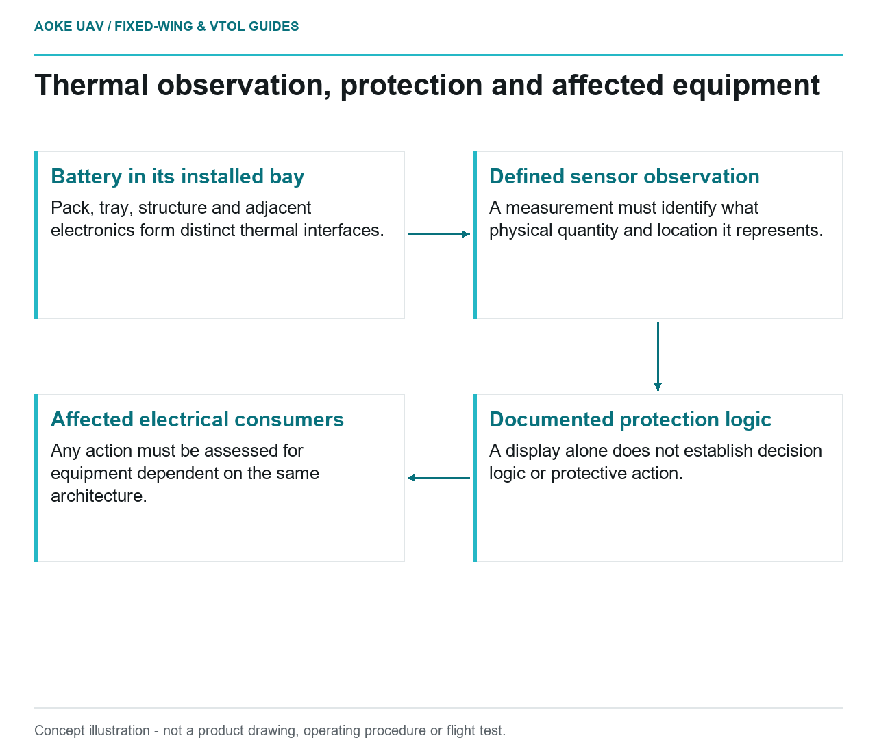
- Battery in its installed bay: Pack, tray, structure and adjacent electronics form distinct thermal interfaces.
- Defined sensor observation: A measurement must identify what physical quantity and location it represents.
- Documented protection logic: A display alone does not establish decision logic or protective action.
- Affected electrical consumers: Any action must be assessed for equipment dependent on the same architecture.
In a hypothetical large fixed-wing mapping UAV, a battery compartment sits beside composite structure and survey electronics. A supplier describes the chemistry as suitable for demanding applications, but the installation requirements are incomplete. The engineering review should resist turning that broad claim into a bay design. This article frames the thermal interfaces and documentation questions that remain, without offering a containment recipe, charging setting or claim that any proposed installation is safe.
Heat generation and operating environment
Ask for the exact pack’s operating and installation documentation, including the conditions to which its evidence applies. Distinguish normal heat-management questions from abnormal battery-failure questions. A report about ordinary temperature behavior should not be presented as proof of protection against a different hazard. Conversely, a hazard-mitigation statement does not by itself characterize normal operation through the proposed mission profile.
FAA AC 20-184A discusses rechargeable lithium battery thermal instability and the need to consider battery systems in the aircraft environment.[1] The document is certification-oriented guidance with a specific regulatory context, not approval for this civil UAV. It supports examining the installed system rather than relying on chemistry alone; it does not supply the hypothetical pack’s limits, heat generation or verified protection behavior.
Adjacent structure and equipment
For this fixed-wing example, map the interfaces between pack, tray, surrounding composite, cable routes and survey electronics. Ask which installation drawings and assessments cover those relationships. Identify any proposed change to access panels or equipment placement that is absent from the supplied evidence. This is a request for configuration traceability, not a recommendation to move the battery or add an improvised barrier.
The FAA guidance addresses protection of structure and critical systems in its battery-equipment flammability discussion.[1] Do not convert that discussion into a universal wall material, separation distance or vent arrangement. The hypothetical integrator still needs the applicable pack and aircraft requirements and the engineering evidence for their chosen arrangement. A drawing of empty space around the pack is not the same deliverable as a supported installation argument.
Monitoring and protection architecture
List the questions separately for measurement, decision logic and protective action. What does each sensor observe? Which device interprets it? Which loads or charging paths are affected by the resulting action? Request the associated part identities and document revisions. Keeping those roles separate prevents a telemetry display from being mistaken for a complete protection system or an isolated protection feature from being called aircraft-level mitigation.
For the large fixed-wing survey scenario, ask how any documented protective action interacts with equipment that depends on the same electrical architecture. Do not invent a cutoff value or suggest bypassing protection to preserve a mission. Where the response is not defined by applicable documentation, the article’s conclusion must remain an unresolved integration question. An OEM statement about the pack alone may leave that aircraft-level interaction open.
Hazard assessment and applicable approval data
Request a package that ties the physical installation, electrical architecture, hazard assessment and maintenance information to the same configuration. AC 20-184A discusses installation particulars, wiring information, configuration control and continued-airworthiness instructions.[1] Those topics help structure the request, but do not establish which certification basis governs this particular aircraft. Determining applicability is a separate responsibility, not something a general technical explainer can grant.
A useful review outcome identifies the missing evidence owner and the claim affected by each gap. For example, absent adjacent-equipment requirements prevent closing that interface even if pack identity is known. This makes the hypothetical fixed-wing decision more precise than calling the whole chemistry good or bad. Until the exact installation is substantiated, retain clear boundaries around normal cooling, abnormal hazards and maintenance; none should be inferred from the others.
Related reading
- Hot-Wet Exposure and Composite Airframe Evidence
- Cooling a Fixed-Wing Propulsion Bay: Evidence Before Ducts