Concept illustration
Read diagram notes
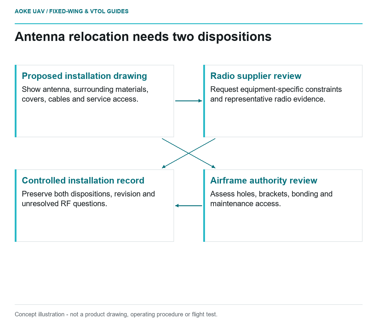
- Proposed installation drawing: Show antenna, surrounding materials, covers, cables and service access.
- Radio supplier review: Request equipment-specific constraints and representative radio evidence.
- Airframe authority review: Assess holes, brackets, bonding and maintenance access.
- Controlled installation record: Preserve both dispositions, revision and unresolved RF questions.
Suppose a large fixed-wing environmental-survey aircraft needs a revised telemetry antenna location after its payload bay changes. A convenient flat mounting surface is only a starting point. The hypothetical integration review has two separate owners: the airframe authority for the structural installation and the radio supplier for installation-specific radio performance. This article develops an evidence request, not an antenna layout. No applicable radio installation manual or measured transmission data was supplied, so it does not predict attenuation, shielding or operating range.
Conductive structure and installation context
Identify the proposed antenna, its mounting hardware and the exact airframe region before comparing locations. Ask the radio supplier what information it requires about surrounding materials and installed geometry. The review should include the completed configuration, rather than treating an antenna catalogue page as evidence for every aircraft. Do not turn the word carbon into a numerical radio-performance claim.
FAA composite guidance describes carbon composites as electrically conductive in its lightning discussion, while distinguishing resins and other reinforcement systems. That is material context, not an RF installation analysis. The document concerns US certificated aircraft structure and cannot establish the performance of the hypothetical fixed-wing communications link. [1] Keep conductivity, antenna performance and structural suitability as distinct questions in the supplier correspondence.
Clearance and cable routing questions
Create a proposed installation drawing showing the antenna position, nearby covers, cable route, connectors and service access. Ask the radio supplier to identify required clearances and routing constraints for the exact equipment. If the supplier cannot assess the arrangement without a representative installation test, record that dependency rather than estimating an acceptable distance from an unrelated aircraft.
For the civil fixed-wing team, the drawing should also show configuration alternatives under consideration. A location that keeps a cable short may differ from one that preserves hatch access. Document the tradeoff without ranking it from unverified assumptions. Request the conditions under which the radio supplier’s evidence remains applicable, including which accessories and covers were present. This makes later changes visible instead of leaving performance tied to an undefined installation.
Mount changes and structural review
Ask the airframe authority whether the proposed hole, bracket or bonded attachment is already covered by its installation provisions. Record the opening geometry and attachment configuration as design inputs, not as instructions to manufacture them. FAA guidance treats holes, joints and other structural discontinuities within a building-block substantiation approach; it also emphasizes qualified processes for structural bonding. [1]
A successful radio check would not resolve an undocumented structural attachment. Equally, an acceptable bracket would not demonstrate antenna performance. For this hypothetical large fixed-wing integration, require a disposition for each side before calling the drawing complete. Do not assume that a removable fairing eliminates structural review: its attachment still has an interface with the aircraft, and the applicable evidence must identify that interface.
Evidence required from radio and airframe suppliers
Organize the request around a configuration-controlled package: equipment identity, installation drawing, radio evidence, airframe disposition and maintenance access. Ask who approves changes to each item and how the team will recognize an obsolete drawing. Keep unresolved RF questions explicit; no universal range, coverage or reliability assurance follows from the structural source used here.
FAA maintenance guidance calls for inspection and repair access appropriate to composite structural details. [1] In this review, that becomes a question about reaching the antenna attachment and inspecting the surrounding structure without unauthorized disassembly. The final fixed-wing installation record should state what was assessed and what remains unverified. It should not imply approval for a mission, operating distance or regulatory category merely because the antenna fits and the connector can be reached.
Related reading
- Nonstructural Radomes: Separate RF and Mechanical Requirements
- Power Routing and Navigation Sensor Interference