Concept illustration
Read diagram notes
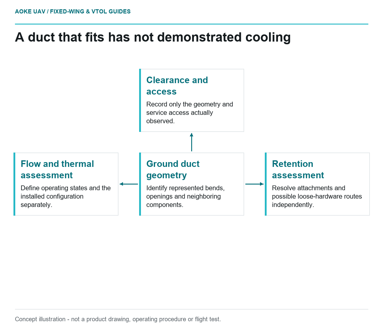
- Ground duct geometry: Identify represented bends, openings and neighboring components.
- Clearance and access: Record only the geometry and service access actually observed.
- Flow and thermal assessment: Define operating states and the installed configuration separately.
- Retention assessment: Resolve attachments and possible loose-hardware routes independently.
Suppose a printed duct fits neatly inside the propulsion bay of a large civil fixed-wing aircraft. The cowl closes and the installation team can reach the intended attachment points. That is a useful ground observation, but not a cooling result. In this hypothetical integration review, the prototype is a geometry aid used to identify the evidence needed before selecting a production duct or changing the aircraft installation.
Flow path and pressure-loss questions
Define what the prototype actually represents: inlet and outlet locations, neighboring components, bends, openings, and any simplified internal features. Record the model revision and inspected geometry. Formlabs recommends comparing printed aids with the CAD definition and testing their functional performance. That supports checking the artifact used for the review, not inferring a cooling-air quantity from its apparent fit. [4]
Ask the system designer where the cooling-air assumptions originate. What operating states and surrounding flow conditions must the final installation address? Which restrictions or bypass paths are represented in the evaluation? These proposed questions avoid treating a visible open passage as proof of adequate flow. No duct dimensions, pressure-loss coefficients, or installed airflow values are established by the sources used here.
Material exposure and heat sources
A geometric prototype may use a material selected for convenient fabrication rather than for its final operating exposure. Keep that distinction explicit. Request the production material definition and the aircraft program’s temperature, fluid, and service requirements. Neither the label engineering polymer nor a supplier’s generic temperature claim defines the suitability of a completed duct within this propulsion bay.
NASA-STD-6030 asks for part-specific operational environments and material/process identity within its spaceflight documentation. Its separation of as-built and post-processed conditions is another reminder to identify the actual finished state being assessed. These are contextual evidence-management concepts, not UAV material allowables or a qualification method for this duct. [5]
Attachment and debris risks
Use the fixed-wing bay review to examine removal paths, assembly access, neighboring moving equipment, and the route of any loose hardware. Ask who owns retention, fastener interface design, and inspection access in the production installation. A ground mockup can make those questions visible, but an easily assembled printed shell does not demonstrate attachment capability under the aircraft’s required environments.
The proposed review record should distinguish an observed interference from a predicted failure question. For example, document that a represented service connector cannot be reached with the mockup installed; separately ask whether a retained duct failure could create debris in another system. The second statement needs engineering assessment. It should not appear as a tested result or a reason to prescribe an unverified attachment modification.
Validation plan for the installed system
Before using any cooling observation, identify the evaluated configuration, operating conditions, instrumentation, acceptance criteria, and responsible reviewer. A bench arrangement and a complete aircraft installation answer different questions unless their applicability is demonstrated. This is a proposed planning structure, not a claim that an evaluation has occurred or a recommendation to operate an unvalidated propulsion system. Include the intended bay closure and surrounding installation in that applicability discussion.
For this large fixed-wing scenario, the correct outcome may be a revised envelope plus an open cooling verification plan. Keep the prototype ground-only unless the applicable design and release process explicitly changes its status. Close each issue with evidence that addresses that issue: geometry evidence for clearance, material/process evidence for the actual duct, and installation-specific evidence for cooling and retention. A single word such as fits cannot replace those separate conclusions.
Related reading
- Cooling a Fixed-Wing Propulsion Bay: Evidence Before Ducts
- Payload Bay Cutouts in Composite Fuselages