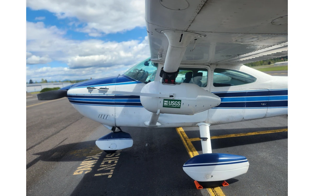
A sensor that fits inside an aircraft bay is not necessarily an integrated mapping payload. Consider a hypothetical large fixed-wing survey airframe being evaluated before a camera purchase. The procurement team needs a configuration-specific interface record: what the camera sees, how it is retained, where its power and data travel and how its measurement geometry remains traceable after servicing.
Envelope and field of view
The RedEdge-MX integration guide explicitly connects mounting location with the lenses’ viewing cone and a clear downward view. It also discusses orientation, protection during landing and the separate placement of the DLS 2. These are requirements and recommendations for that documented model and revision, not a common bay standard for every survey sensor. [20]
For this hypothetical fixed-wing bay, the mechanical review would request the complete installed envelope, including connectors, cable exits and removal space. The optical review would overlay the actual field of view with the bay opening and nearby aircraft structure. A drawing showing only the camera housing would leave both questions incomplete.
The team’s evidence request would cover the full intended configuration, not just the camera on a bench. Protective provisions and any optical window would need their own applicability review. The example does not establish that a particular recess, window or fairing is suitable.
Mass and structural interfaces
The proposed integration checklist would identify camera, accessories, wiring and retention hardware as one installed assembly. It would request the approved airframe interface documentation and the sensor supplier’s mounting information. Those records would determine the actual structural assessment; no allowable load or fastening recipe is supplied here.
Service actions would also be considered. If the payload can be removed between fixed-wing sorties, the project would need a defined method for restoring its installation identity. Whether remounting requires new measurements or calibration would depend on the actual design and its demonstrated repeatability, not on the convenience of the attachment.
Power and data paths
The RedEdge-MX guide distinguishes power input, trigger interfaces, serial communication and Ethernet, and discusses power at the camera after wiring losses. It also states that capture behavior depends on storage performance. These details illustrate why naming a connector or nominal supply is not a complete interface definition. The guide is not a universal pinout and its specifications must not be transferred to another model. [20]
The hypothetical integrator would prepare an interface list showing the supplier requirement and the aircraft-side provision for every connection. Simultaneous camera, navigation and accessory demands would be reviewed for the actual mission configuration. Questions about peak demand, grounding, signal compatibility and interruption behavior would go back to the applicable manuals and responsible engineers.
Data paths would be traced from command to recorded observation and then to retained project files. A functioning communication link would not establish that each intended capture was stored. An acquisition demonstration would need to exercise the chosen configuration and preserve its event and file evidence; no successful test is claimed in this example.
Calibration and service access
USGS imagery guidance connects geometric calibration with camera parameters, acquisition geometry and control evidence. It also recommends preserving equipment identities, settings and calibration information with the data. That makes configuration traceability part of the measurement workflow rather than an administrative afterthought. [6]
The example review would ask whether technicians can inspect lenses, retrieve storage and access connectors without disturbing an important measurement interface. If a service action changes the camera configuration, the project record would identify which calibration assumptions need review. Accessibility should be assessed together with the actual retention design, not used to bypass it.
The purchase decision would remain open until the bay, sensor and processing responsibilities are allocated. Physical fit, electrical operation, data completeness and demonstrated measurement quality are different milestones. A checklist can expose missing evidence, but it cannot substitute for aircraft-specific engineering or turn an untested installation into an approved large fixed-wing mapping system.
Related reading
- Removable Payload Trays Without Hidden Structural Assumptions
- Payload Power Transients and Survey Sensor Integration
Sources
- [20] MicaSense RedEdge-MX and DLS 2 Integration Guide
- [6] Guidelines for Calibration of Uncrewed Aircraft Systems Imagery
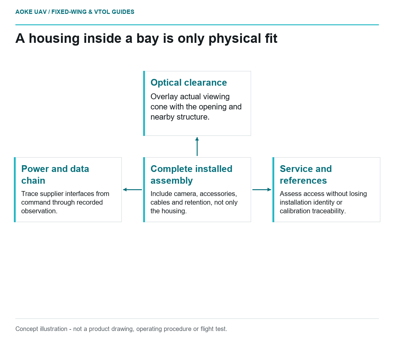
Visual summary
Concept illustration
Read diagram notes
- Complete installed assembly: Include camera, accessories, cables and retention, not only the housing.
- Optical clearance: Overlay actual viewing cone with the opening and nearby structure.
- Power and data chain: Trace supplier interfaces from command through recorded observation.
- Service and references: Assess access without losing installation identity or calibration traceability.