In a hypothetical large fixed-wing mapping aircraft, a load-bearing spar and an antenna cover appear on the same materials list. A procurement discussion asks whether both should contain more carbon. That is the wrong starting point for this review. The two regions have different functions and need evidence for their actual laminate and installation. No candidate laminate datasheets or comparative tests were provided. The article therefore develops a comparison brief rather than recommending glass, carbon or a hybrid as the superior material.
Stiffness and mass objectives
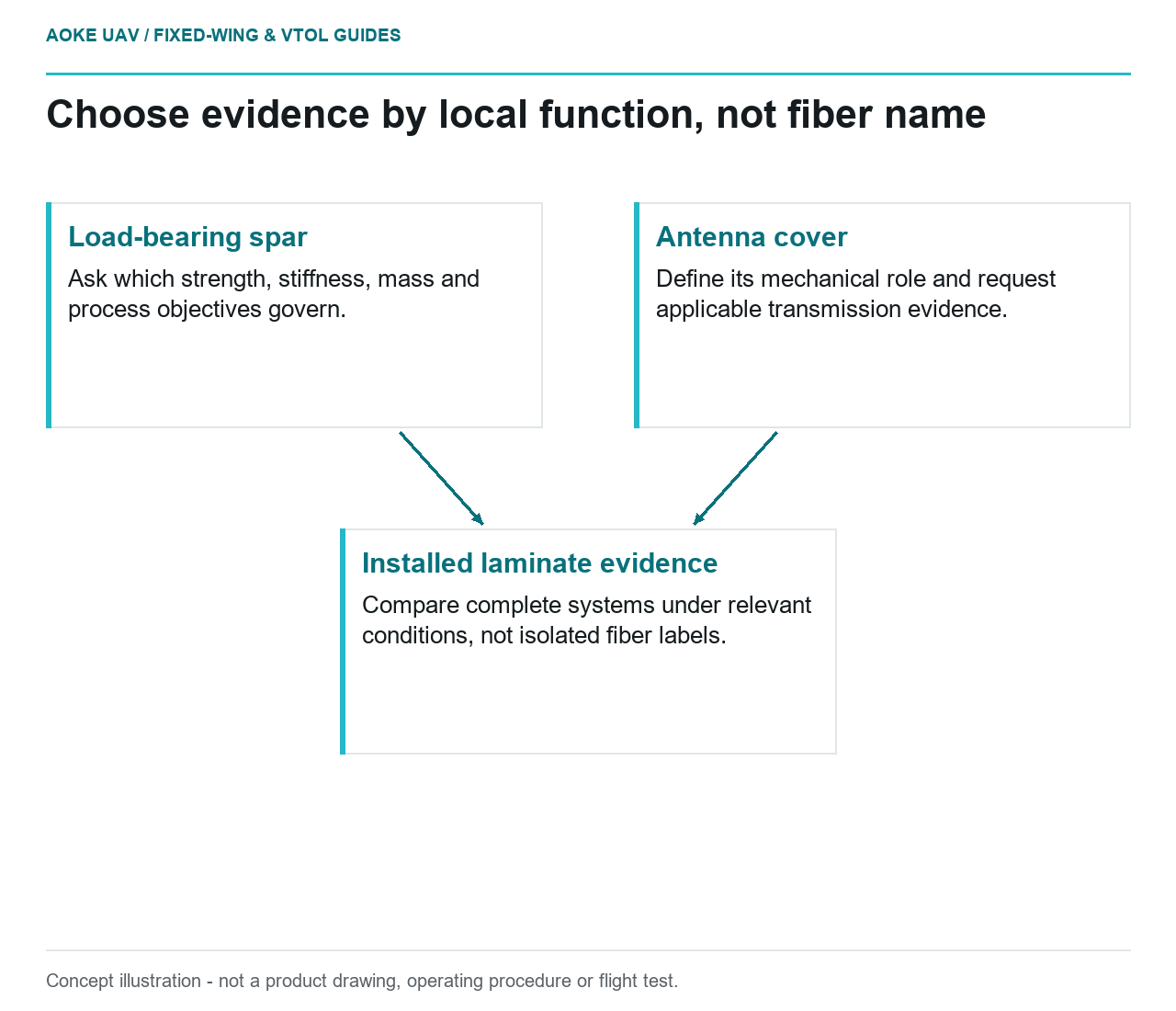
Define the function of each proposed component before collecting material numbers. For the spar, ask the design authority which stiffness, strength, mass and manufacturing objectives govern its actual design. For the cover, ask what mechanical role is required and what evidence the antenna supplier needs. Keep those requirement sets separate even if a single supplier makes both parts.
FAA composite guidance states that laminated-system design values should be established at the laminate level, or through lamina data with test-validated analysis. It also ties values to representative materials and processes. [1] In this US certificated-aircraft context, fiber identity alone is not a complete structural design definition. For the hypothetical fixed-wing team, a single catalog modulus should therefore be recorded as limited material information, not as a component selection verdict.
Electrical and environmental interfaces
Identify electrical and metal-contact interfaces as separate review items. The FAA discusses isolation layers between some carbon-composite and metal combinations to address corrosion, and distinguishes reinforcement systems in its lightning discussion. [1] Those statements provide context for asking how a specific interface is designed. They do not specify an isolation construction for this UAV or predict radio behaviour around its antenna.
Ask the airframe and equipment suppliers what installation-specific evidence is needed. Do not label a glass cover radio-transparent without applicable transmission data, and do not call carbon an installed lightning-protection system. For this large industrial fixed-wing scenario, retain both as unresolved performance questions until the relevant configuration is assessed. No shielding factor, transmission loss or corrosion-life comparison follows from the material names.
Load-bearing versus covering functions
The review drawing should state whether each item carries flight loads, retains equipment, encloses an opening or provides another documented function. Ask what happens at its attachment and what evidence covers the supporting structure. A light cover can still have an installation interface requiring review; a load-bearing member cannot be assessed only as a bare laminate coupon.
FAA structural guidance treats local features such as holes and joints within configuration-specific substantiation. [1] Accordingly, compare proposed material systems in the component definition rather than as interchangeable sheet stock. In the hypothetical fixed-wing program, replacing a carbon item with glass, or the reverse, should trigger a documented applicability question. The article supplies no basis for assuming equivalent geometry, service behaviour or attachment requirements.
Evidence for the complete laminate
Request a comparison package identifying reinforcement, resin, architecture, processing route, conditioning, test method and the relevant assembly. Ask which results are measured and which are derived through a validated method. Retain the limitations alongside the numbers, especially if the two proposals were tested under different conditions or represent different maturity levels.
The FAA emphasizes environmental evidence and stable, repeatable material/process definitions when developing design values. [1] Use that to structure the request, not to invent a relative performance result. A defensible fixed-wing selection record might conclude that evidence remains insufficient to compare the candidates. That is more informative than declaring one fiber universally best. The decision should explain how the chosen system satisfies the local function and how its complete installed configuration is supported, with any missing evidence still visible.
Related reading
- Nonstructural Radomes: Separate RF and Mechanical Requirements
- Chopped-Fiber Prints Are Not Continuous-Fiber Wing Laminates
Sources
Visual summary
Concept illustration
Read diagram notes
- Load-bearing spar: Ask which strength, stiffness, mass and process objectives govern.
- Antenna cover: Define its mechanical role and request applicable transmission evidence.
- Installed laminate evidence: Compare complete systems under relevant conditions, not isolated fiber labels.