Concept illustration
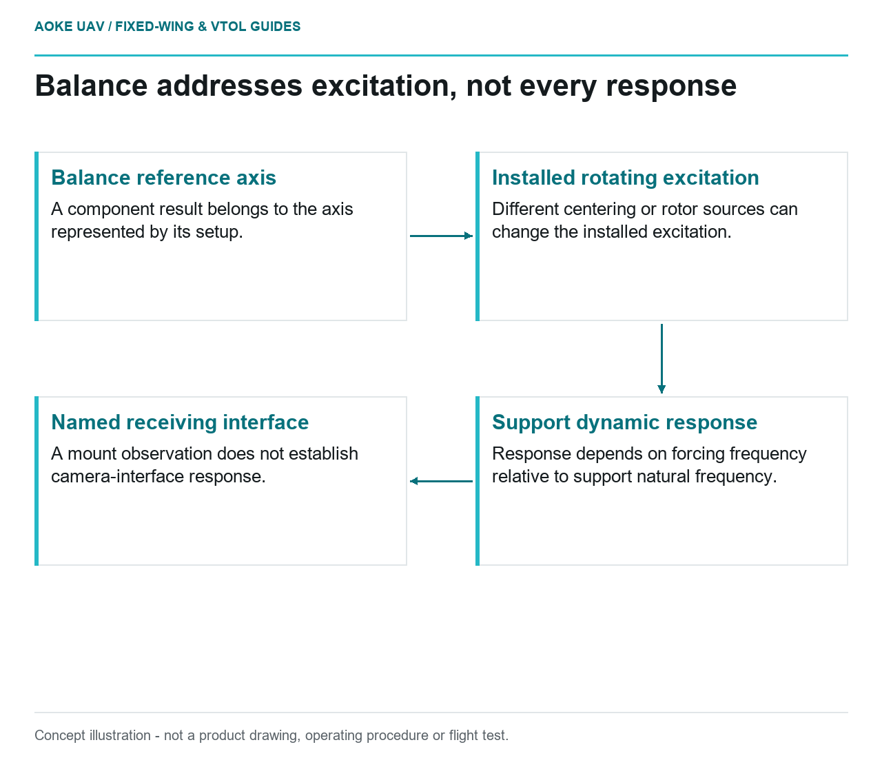
Read diagram notes
- Balance reference axis: A component result belongs to the axis represented by its setup.
- Installed rotating excitation: Different centering or rotor sources can change the installed excitation.
- Support dynamic response: Response depends on forcing frequency relative to support natural frequency.
- Named receiving interface: A mount observation does not establish camera-interface response.
A hypothetical large fixed-wing survey aircraft has a propeller balance report, yet its installed vibration evidence remains unresolved. The report can be valid without answering the installation question. To see why, distinguish the mass distribution referred to a component axis from the response of a supported, rotating assembly. This explainer uses OEM instructions and an explicitly simplified dynamics comparison, not an GAUTEN test or a method for balancing a propeller.
Component balance and installed dynamics
APC’s actual balancing advisory distinguishes its precision-molded rear hub reference from the drilled through-hole, which may not be straight. Its separate centering advisory identifies the locating ring as the centering feature for the documented installation.[1] The important lesson is reference sensitivity: a balance result refers to the axis represented by its setup, not every axis on which someone might mount the part. The OEM document must govern any real maintenance; no correction procedure is reproduced here.
University of Alberta’s rotating-imbalance model represents an eccentric rotating mass that excites motion of a supported machine body. It separates the excitation from the machine’s displacement response.[2] Thus component unbalance concerns a source of rotating excitation; installed vibration concerns what the surrounding system does with excitation. Reducing one source does not characterize the receiving structure or eliminate all possible sources.
Mount and bearing interfaces
Consider an original thought experiment: the same propeller is referred correctly to its intended axis in one assembly, but a second hypothetical assembly locates it about a different axis. Its component report has not changed. The report alone cannot establish the second assembly’s centering. This is an applicability problem, not evidence that either actual propeller needs material removed. APC’s reference distinction makes this comparison concrete without supplying an aircraft installation approval.[1]
Even with appropriate centering, a propeller report does not describe the motor rotor and bearings. Maxon’s motor reference identifies residual rotor imbalance and bearing load as considerations in permissible speed and bearing service life for its documented motor families.[3] This is a separate component boundary, not an allowable bearing load or inspection criterion for the survey aircraft.
For this hypothetical large fixed-wing installation, a motor-mount response measurement would answer a question at that location. It would not retroactively measure the propeller’s balance, nor establish camera-interface response. Treating all three as a single vibration result would confuse the source, the transmission path and the receiving location.
Operating-point dependent response
The Alberta spring-mass treatment shows that forced response depends on excitation frequency relative to the supported system’s natural frequency. Near resonance, the ideal undamped model predicts a strongly amplified response; the rotating-imbalance example also makes excitation speed-dependent.[2] This is a teaching model, not a prediction that an aircraft has infinite vibration. Its ideal assumptions cannot supply an installed acceptance value.
Use that relationship for a bounded comparison. Imagine the same residual excitation acting on two conceptual supports, one whose natural frequency is well separated from the forcing frequency and one much closer. Holding the component result fixed does not hold their responses fixed. Conversely, a quiet observation in one operating state does not characterize another state with a different forcing relationship. This comparison explains why a balance certificate cannot stand in for installed dynamics; it does not identify a safe speed or instruct a speed sweep.
Evidence beyond a static balance claim
In the illustrative review, a correctly identified component report could support the narrow conclusion that the assessed propeller met the report’s stated balance criterion about its stated reference. An installed record could support a different conclusion: what a particular measurement chain observed at a named location and operating condition. Neither conclusion automatically proves the other, and no balance criterion has been invented here.
The missing aircraft decision is therefore not whether to discard useful balance evidence. It is whether the installation has substantiation for its own structural, navigation and payload requirements. A favorable component result reduces one uncertainty while leaving those receiving-interface questions open. Cross-team correlation belongs to the linked interface article; this explanation establishes the physical reason that a balanced propeller is not whole-system vibration clearance.
Related reading
- Propulsion Vibration Across Structure and Survey Payloads
- Vibration and Image Quality in Fixed-Wing Payloads