Concept illustration
Read diagram notes
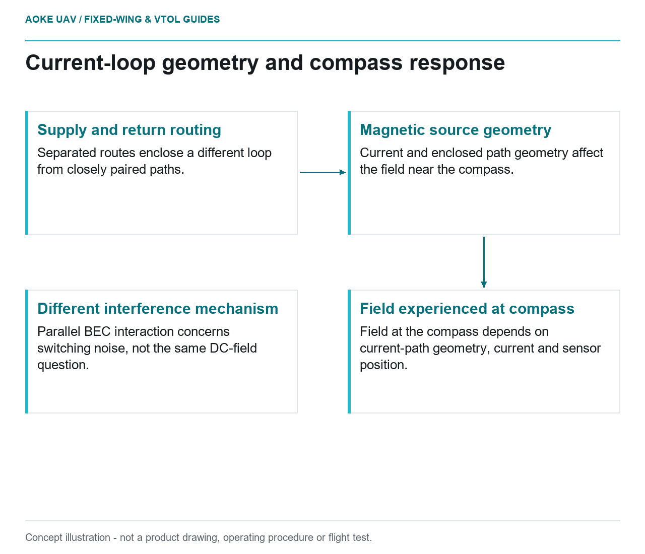
- Supply and return routing: Separated routes enclose a different loop from closely paired paths.
- Magnetic source geometry: Current and enclosed path geometry affect the field near the compass.
- Field experienced at compass: Field at the compass depends on current-path geometry, current and sensor position.
- Different interference mechanism: Parallel BEC interaction concerns switching noise, not the same DC-field question.
Consider a hypothetical large industrial fixed-wing VTOL aircraft with propulsion wiring and navigation sensors inside a conductive fuselage. Two proposed revisions both claim to reduce interference: moving a compass higher and changing a servo supply. They address different mechanisms. This worked comparison separates a documented parallel-BEC supply problem from magnetic effects of current-path geometry, then distinguishes both from GPS reception and mounting requirements. It reports no GAUTEN installation or test result.
Navigation sensors and nearby current paths
ArduPilot’s Pixhawk power page warns against paralleling servo-rail supplies: unequal BEC outputs can interact, some BECs can oscillate, and resulting switching noise can affect GPS and RC reception.[1] The warning concerns that supply arrangement. It is not evidence that any high-current cable necessarily causes GPS errors, or that moving a compass fixes interacting regulators.
ArduPilot’s separate magnetic-interference guidance identifies another mechanism: compass disturbance associated with DC power distribution and wiring. Its current-loop discussion connects magnetic field to current, loop geometry and sensor position; it recommends keeping return and source paths close.[3] This is the relevant starting point for reviewing the propulsion route, not the parallel-supply warning alone.
For an original qualitative comparison, suppose one fixed-wing layout carries the supply conductor along one side of the equipment bay and its return along the other. A second proposed layout keeps the corresponding paths close over that same bay. With other conditions held comparable, the second proposal addresses the enclosed current-loop geometry identified by the guidance.[3] That gives the reviewer a physical variable to compare, without claiming a measured compass improvement or prescribing a finished harness.
Mounting and conductive structure
Moving the compass away from a current path and reducing the path’s enclosed area are different changes. One changes the observer’s position; the other changes the source geometry. ArduPilot discusses both, and explicitly says aluminum shielding does not remove the primary DC interference from the distribution wiring.[3] Thus a conductive cover cannot simply be credited as a cure for that magnetic mechanism.
A third change concerns nearby mounting hardware. ArduPilot’s UBlox GPS-plus-compass installation page distinguishes clear sky view for GPS from distance to interfering magnetic fields for the compass; it also calls for avoiding nearby iron-containing objects and specifies module orientation.[4] Those are concrete installation variables, not interchangeable versions of one clearance rule.
In the hypothetical fixed-wing bay, replacing a nearby iron-containing bracket would address the mounting-material question, not prove that the supply/return loop was acceptable. Likewise, pairing a route would not establish GPS sky visibility. The drawing should show these variables separately so a favorable argument for one cannot silently close the others.
Model-specific installation requirements
The UBlox page gives guidance for its GPS/compass installation context; it is not the OEM installation authority for every navigation assembly.[4] Its numeric clearance is not adopted here as a universal large-aircraft design value. The actual selected sensor, orientation and installation constraints still determine which comparison applies.
The December 2021 RedEdge-P/DLS 2 guide adds a distinct camera-system example: its general DLS guidance calls for clear sky view and avoiding GPS-interfering equipment, while its fixed-wing subsection addresses shadows, reflections and installation at the fuselage high point where possible.[2] These concern reception and light-sensor geometry, not a demonstrated compass-error threshold. The guide’s separate multirotor advice is not transplanted to this fixed-wing scenario.
Evidence from the installed configuration
The hypothetical review would classify each proposed revision before choosing its evidence: supply topology for the parallel-BEC concern; current-path geometry and compass location for magnetic susceptibility; mounting materials and orientation for the module installation; sky visibility and interfering equipment for GPS. A single statement that navigation works would not distinguish which question had actually been examined.
Retain the paired supply/return route, branching locations, sensor reference position and mount revision alongside the assessed operating configuration. For a fixed-wing VTOL, the proposed comparison should identify whether the relevant record concerns lift propulsion or cruise propulsion rather than assuming one arrangement represents both. These are original evidence-planning distinctions, not motor-running or fault-injection instructions.
The outcome is a causal layout review, not a separation-distance recipe. It explains why a regulator change, a revised current loop and a sensor-mount change cannot substitute for one another. Installed navigation performance remains unverified until the applicable hardware documentation and configuration-specific evidence support it.
Related reading
- Antenna Placement Around Carbon Composite Airframes
- Reviewing GNSS Solution Quality for Survey Trajectories