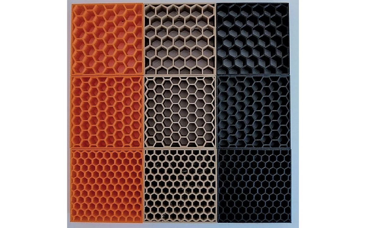
A lightweight interior pattern looks efficient beneath a large wing mold surface. But a slicer’s infill percentage is not an acceptance result. In this hypothetical civil fixed-wing tooling review, the proposed construction must preserve the layup geometry through the defined manufacturing process. The reviewer needs a complete description of the shell, internal support, local hardware, and processing conditions before judging whether material reduction is justified.
Shell and internal support functions
Use the terminology of the actual equipment and process guidance. Stratasys distinguishes shell-style and sparse-style tooling and explains that its sparse construction discussion refers to particular Insight fill patterns. It specifically warns that the pattern named simply sparse in that software is not recommended for its composite tooling applications. A familiar word can therefore hide materially different construction definitions. [3]
For this fixed-wing tool drawing, identify the layup surface, backing construction, boundary conditions, and internal features rather than record only a percentage. Ask which geometry the process expects to remain controlled and what supports that geometry at each stage. These are review questions for the proposed design, not a claim that a given pattern is weak or a recommendation to copy another tool’s wall thickness.
Pressure and thermal load conditions
The guide ties tool construction to cure parameters and the bagging approach, and discusses susceptibility of sparse construction to crushing under inappropriate envelope-bagging conditions. Its supporting density guidance is limited to specified material, fill patterns, slice height, geometry, and test conditions. [3] Do not lift a raster spacing from that table and present it as an allowable for any large wing mold.
Instead, have the tooling authority define the actual process conditions and the evidence needed to represent them. Identify how the complete tool is supported, where pressure differences apply, and what temperature history the manufacturing process imposes. A room-temperature hand check cannot resolve an unspecified hot processing case. No consolidation pressure or thermal cycle is prescribed here for the proposed aircraft panel.
Local support near hardware
An overall fill description can overlook features with distinct functions. Stratasys discusses localized reinforcement and different construction for bushings, inserts, machining faces, and the bulk tool. [3] That supports treating the tool as a collection of controlled features rather than assuming a single infill setting adequately defines every region. The detailed recommendations remain tied to the OEM process and intended tooling application.
In the hypothetical fixed-wing mold, mark the interfaces used for joining, locating, clamping, or handling and request evidence for their local construction. Ask what remains after machining or finishing and how the feature will be inspected. Do not assume that a reinforced insert area establishes the surrounding shell’s capability, or that a strong shell independently validates an attachment assembled into a different internal pattern.
Inspection and process qualification boundaries
Retain the controlled build definition alongside finished-tool inspection. Identify which internal features can be confirmed through manufacturing records and which acceptance questions require additional evaluation chosen by the responsible authority. The article does not propose a non-destructive inspection method or claim that an external scan can verify hidden raster continuity. State the limits of the available evidence explicitly.
For a large fixed-wing program, the useful decision is whether this complete construction is supported for its defined tool function. Lightweight geometry, a supplier image, and a familiar infill percentage are inputs to that review, not proof of performance. Keep tool acceptance separate from acceptance of the composite airframe part later made on it, and revisit the evidence when material, pattern, processing, or support conditions change.
Related reading
Sources
Visual summary
Concept illustration
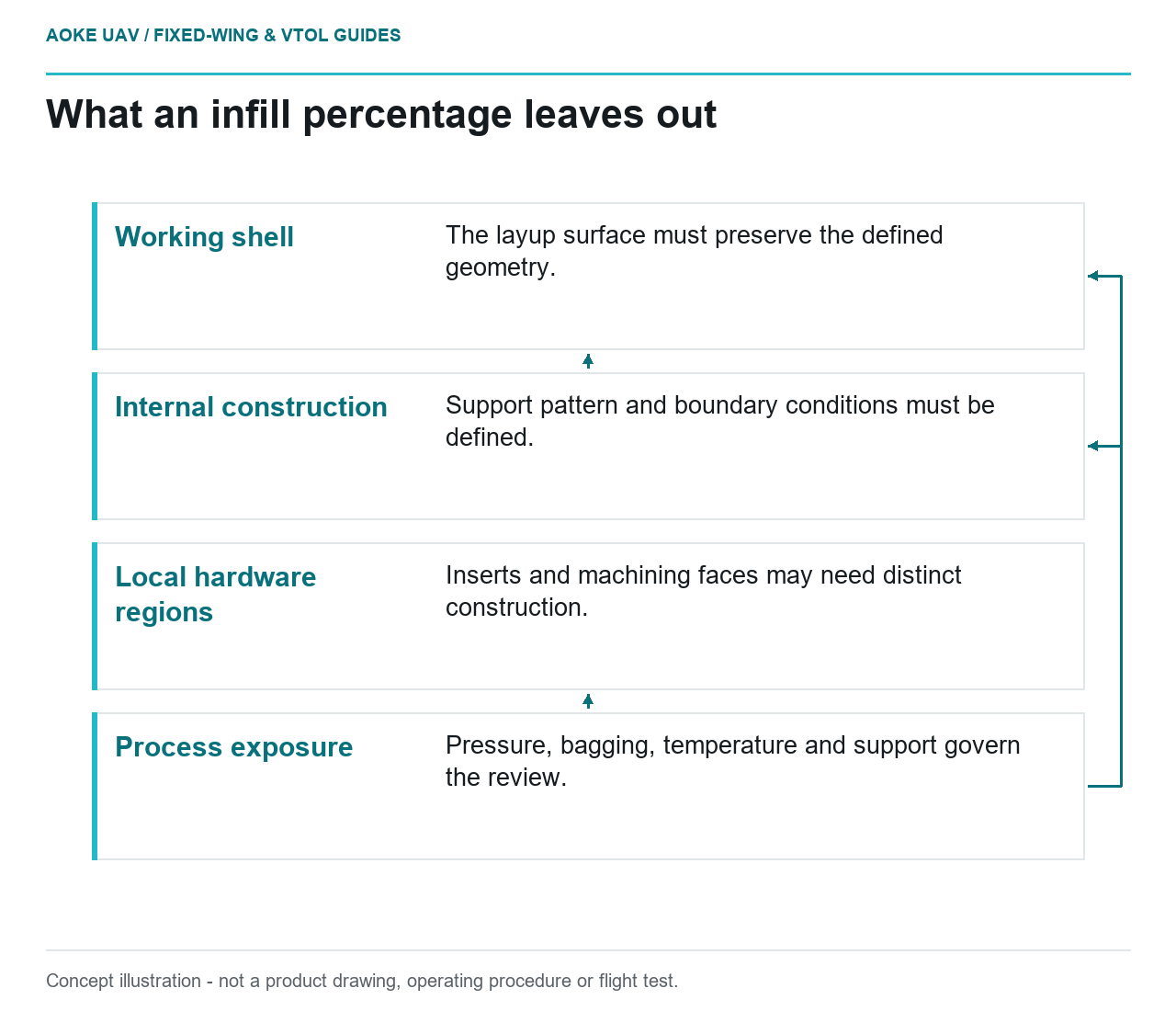
Read diagram notes
- Working shell: The layup surface must preserve the defined geometry.
- Internal construction: Support pattern and boundary conditions must be defined.
- Local hardware regions: Inserts and machining faces may need distinct construction.
- Process exposure: Pressure, bagging, temperature and support govern the review.