Concept illustration
Read diagram notes
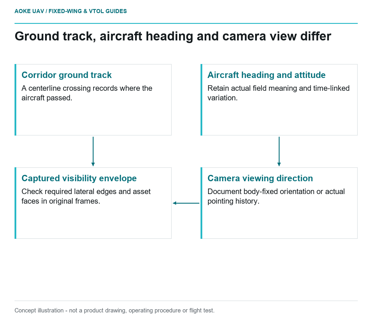
- Corridor ground track: A centerline crossing records where the aircraft passed.
- Aircraft heading and attitude: Retain actual field meaning and time-linked variation.
- Camera viewing direction: Document body-fixed orientation or actual pointing history.
- Captured visibility envelope: Check required lateral edges and asset faces in original frames.
Track direction versus aircraft heading
Following the route is not the same question as pointing the camera at the required evidence. In this hypothetical civil monitoring assignment, a large fixed-wing aircraft follows an industrial corridor while the owner expects imagery of a narrow strip and selected side-facing features. The review must distinguish ground track, aircraft heading and camera viewing direction. Treat these as separate quantities in the acquisition brief rather than calling all of them the flight direction.
Crab describes a heading offset used while maintaining a ground track in crosswind. Here that concept frames an observability question, not a piloting instruction. Before comparing records, establish what each logged field means. ArduPilot’s Plane documentation provides a useful example of configuration-dependent interpretation: an airspeed reading can be displayed or logged without being used in control. [1] Similarly, this proposed review would not assume that a convenient heading label directly describes camera orientation.
Camera orientation and ground footprint
For the scenario, ask the integrator to sketch three items together: the corridor, the aircraft attitude and the camera’s view. Record whether the camera is fixed to the aircraft or uses a documented pointing system. If its orientation follows the body, a changed heading should be included when testing the corridor visibility envelope. If it is stabilised or independently pointed, request evidence of the actual pointing history rather than assuming perfect compensation.
This is a proposed geometry review, not a generic strip-spacing calculation. Check whether the requested asset side, corridor boundary and nearby context are present in the originals. A map showing that the aircraft passed over the centerline does not answer those questions. USGS recommends considering geometric calibration, acquisition and metadata together when judging data suitability. [2] Keep the camera model and any installation assumptions in the review record so the sketch can be checked against the actual payload.
Roll and changing crosswind
A single nominal crab sketch is an incomplete acceptance test for this hypothetical fixed-wing mission. Ask reviewers to examine periods with different recorded heading offsets and attitudes, while checking that timestamps match the corresponding images. WMO explains that wind shear can involve speed or direction changes and describes complex flow around terrain. [3] That context supports asking about variation, but it does not predict a crab angle or establish a crosswind envelope for the aircraft.
Use the original frames to determine whether the camera still covers the required feature class during those periods. In this proposed workflow, a frame can show the corridor center while missing the relevant lateral edge or the chosen side of an asset. Label the limitation in terms of the missing view. Do not infer that all imagery is adequate merely because the aircraft’s route appears well controlled, and do not label an image discrepancy as wind without checking other explanations.
Preserve a distinction between persistent orientation effects and brief interruptions. A sequence might consistently offer the wrong side view, or it might offer the correct view with intermittent unusable sections. The proposed correction is an evidence-design review: verify pointing, event timing and required views before considering reacquisition. This article supplies no universal corridor width, bank angle or crosswind limit. Any operational change requires the applicable aircraft and mission procedures, not a diagram in an explainer.
Review the captured corridor envelope
For handoff, build a route-indexed list connecting each requested view with its supporting images. Mark the visibility envelope actually demonstrated, including partly observed boundaries and occluded features. Retain the difference between heading, track and camera pointing in the accompanying metadata. USGS highlights calibration information and uncertainty as aids to deciding whether data can support a particular use. [2] An attractive mosaic should not erase those qualifications.
The useful large fixed-wing role in this scenario is corridor evidence collection at a feasible observation geometry, not close hovering beside structures. Where the requested view is absent, narrow the deliverable or assign a different inspection method. The final acceptance discussion should concern what the images demonstrate, which assumptions remain unverified and who owns follow-up. It should not claim defect certification, aircraft clearance or permission to operate beyond the applicable authorisation.
Related reading
- Cross-Track Overlap Under Roll and Line-Spacing Variation
- Headwind, Ground Speed and Fixed-Wing Mission Energy