Concept illustration
Read diagram notes
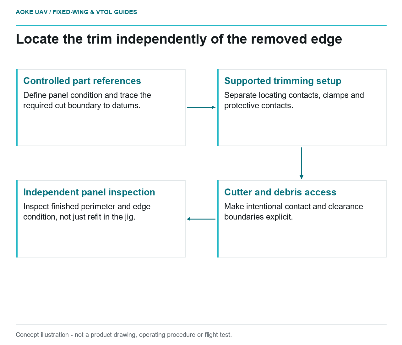
- Controlled part references: Define panel condition and trace the required cut boundary to datums.
- Supported trimming setup: Separate locating contacts, clamps and protective contacts.
- Cutter and debris access: Make intentional contact and clearance boundaries explicit.
- Independent panel inspection: Inspect finished perimeter and edge condition, not just refit in the jig.
A hypothetical composite shop is evaluating a printed trim fixture around a thin wing panel for a large fixed-wing civil mapping aircraft. The proposal has two separate goals: locate the intended perimeter and support the panel during an approved trimming operation. Neither follows simply from matching the panel’s outer shape. This discussion is original editorial planning, not an GAUTEN tool design, cutting recipe or evidence that a flight panel is acceptable.
Support near the cutting region
Define the workpiece condition before proposing supports. Is the fixture intended for a cured skin detail or an assembled panel? Which surfaces are available for contact, and which must remain accessible? In this scenario, the designer would obtain those answers from the controlled part and manufacturing definition rather than from an exterior rendering.
Stratasys treats trim fixtures as ancillary tooling and illustrates deriving tool geometry from the composite part. Its examples are a starting point for considering clearance and tool shape, not proof that an arbitrary printed nest will support a thin fixed-wing skin under cutting loads. [1]
Ask the reviewer to identify unsupported regions and describe the load path into the fixture. Also ask whether the intended support masks an edge that needs visual access. The actual contact distribution and allowable panel loading require project evidence; this article supplies neither a support spacing nor a skin-strength assumption.
Reference surfaces and clamping
Mark locating contacts separately from clamps and protective contacts on the proposed fixture drawing. For the hypothetical wing panel, the cut boundary should be traceable to specified references rather than to a convenient edge that will itself be removed. Agree how the operator establishes seating before the tool approaches the part.
Formlabs recommends checking printed fixtures against CAD and testing how the workpiece seats against locating surfaces and supports. It states that clamping requirements for operations such as milling or drilling depend on operating forces and machine and material conditions. The same review principle is relevant here, without transferring a numerical clamp setting to trimming. [2]
For this fixed-wing application, make potential skin crushing or unwanted shape restraint explicit review questions. If clamping changes the geometry being controlled, the team needs an engineering disposition, not a stronger fastener. Define how contact layers, replaceable pads or inserts affect the tool’s verified condition. Uncontrolled padding should not become an undocumented dimensional correction.
Dust and tool-contact boundaries
Use the proposed trimming sequence to review access for the selected cutting system, approved debris control and safe handling. In this scenario, the review would check that the fixture does not block the intended collection path or conceal contact between the cutter and a fixture feature. Those are review tasks, not a dust-exposure standard or a claim about a validated extraction arrangement.
Formlabs identifies wear and continuous loading as limitations of printed tooling and recommends considering metal or hybrid solutions in high-wear areas. This makes unintended cutter contact and repeated clamp contact relevant concerns, but it does not authorize using a printed edge as a wear guide without application-specific validation. [2]
Keep the boundary between locating aid and cutting element visible in instructions. Where the tool is not meant to contact the fixture, show how that clearance will be checked. Where contact is intentional, obtain specific evidence for the interface. Do not leave that distinction to the operator’s interpretation of a CAD image.
Inspect the trimmed panel separately
In the hypothetical acceptance plan, fixture verification would precede use, while the completed panel would receive its own dimensional and edge-condition inspection under applicable engineering instructions. Fitting back into the same trim fixture would be only an observation, not independent proof of the final result.
Keep records for panel identity, fixture revision, setup condition and any contact or movement anomaly during trimming. Define what requires tool reinspection after wear, a dropped fixture or repair. A new print from the same nominal file still needs acceptance as a physical tool; digital similarity does not document its actual condition.
The useful deliverable is a supported, inspectable trimming setup with explicit limitations. It is not a substitute for approved composite machining data or panel damage criteria. If the aircraft documentation does not define those criteria, the large fixed-wing team must resolve that gap before treating a clean-looking edge as an accepted structural feature.