Concept illustration
Read diagram notes
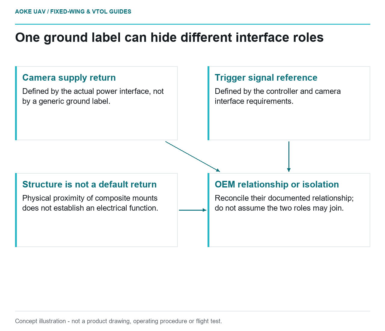
- Camera supply return: Defined by the actual power interface, not by a generic ground label.
- Trigger signal reference: Defined by the controller and camera interface requirements.
- OEM relationship or isolation: Reconcile their documented relationship; do not assume the two roles may join.
- Structure is not a default return: Physical proximity of composite mounts does not establish an electrical function.
A hypothetical large fixed-wing mapping aircraft connects a survey camera to both an aircraft power source and a controller trigger interface. The wiring sketch labels several conductors ground without defining their roles. The review should not resolve that ambiguity by joining every label together or assuming that the airframe is the intended return. The immediate deliverable is an interface-reference map tied to exact OEM documents, not a generic grounding topology.
Signal reference versus power return
Identify the purpose of each conductor in the applicable interface drawing: supply, supply return, signal, signal reference or another documented function. Retain the exact connector and document revision with the definition. The term ground is not sufficient evidence that two interfaces share the same intended connection. If the source material does not establish the relationship, record it as a question for the hardware owners before proposing an interconnect.
In its specific Pixhawk architecture, ArduPilot requires a ground reference alongside ESC signal wiring.[1] This statement concerns that documented controller-to-ESC interface. It must not be expanded into a rule that every payload reference should be connected identically. Its relevance to the fixed-wing review is to identify the reference requirement of each interface rather than treating a signal wire as a complete definition by itself.
Shared references across controller and payload
The RedEdge-P and DLS 2 integration guide includes a caution about distinct power and trigger grounds and discusses isolation in that model-specific context.[2] That example is important precisely because it cannot be reduced to all grounds always join. The guide’s applicable interface sections and figures need to be reconciled for the exact camera revision and proposed aircraft connections; this article does not reproduce a pinout or resolve an unidentified harness.
For the hypothetical fixed-wing installation, ask where the camera’s power source originates, which controller interface provides the trigger and what each OEM says about their relationship. Keep those answers in one controlled record. If different suppliers describe apparently conflicting requirements, the next step is a documented resolution by the responsible integration team and OEMs, not an improvised adapter based on a general article.
Isolation follows applicable documentation
Request the exact interface electrical requirements and the supported interconnection arrangement. An isolation recommendation in one camera guide does not establish the type, rating or wiring of an isolator for another model. Equally, a signal-reference requirement in a controller example does not override a payload-specific caution. Sources should be used to define the scope of each question, rather than selectively choosing whichever sentence makes a proposed wiring shortcut convenient.
For this large fixed-wing survey aircraft, the review should also identify whether the structural installation has any documented electrical role. Do not use composite structure, mounting hardware or shielding as a power return merely because those features are physically nearby. No such arrangement is established by the cited examples. The responsible electrical design needs its own applicable basis and configuration-specific assessment.
Record topology and changes
A useful interface-reference map lists both ends of every relevant connection, the reference defining it and the supporting OEM document. Include revisions to the power source, camera, controller and harness. If the aircraft adds another communications interface, revisit the map rather than assuming that the original arrangement already covers the new reference relationship. This is configuration-control guidance, not a suggested connection sequence.
The fixed-wing handoff should leave no ambiguity about what is documented and what still requires supplier clarification. The cited examples support the need to distinguish interface references, but they do not supply a universal star ground, bond scheme or isolation architecture. The outcome is a traceable design question set with unresolved items owned explicitly, not an electrical compatibility assurance derived from the shared word ground.
Related reading
- Carbon Composite and Metal Interfaces in Damp Service
- Printed Connector Assembly Aids for Payload Harnesses