A hypothetical tooling designer is comparing build orientations for a curved aerodynamic mold used on a large fixed-wing civil survey aircraft. One arrangement looks smoother in the slicer; another appears easier to support and finish. The decision is not simply which face looks best immediately after printing. It concerns the finished, inspectable tool in its intended process. No GAUTEN mold, measured surface result or aircraft-specific print specification is described here.
Stair-stepping on curved surfaces
Stratasys identifies build orientation as an influence on stair-stepping, support-material use, build time and tool performance. Its general recommendation favors arranging layup surfaces to reduce stepping, but its examples also show that different geometries can justify different compromises. A preferred orientation in one illustration is not a universal rule. [1]
For the hypothetical fixed-wing mold, divide the surface review into functional regions: aerodynamic contour, panel-edge reference, flange and measurement targets. Compare each candidate orientation against those regions. Ask where the print leaves finishing work and how that work will be controlled; a single overall appearance score would hide the distinction.
Do not confuse smoother-looking layers with demonstrated contour accuracy. The design review should specify what finished geometry is required and how it will be measured. The project needs its own acceptance criteria rather than borrowing a surface-finish value or machine claim from an unrelated example.
Build direction and mechanical response
The guide states that FDM properties are anisotropic and that orientation influences overall tool performance. It also presents elevated-temperature flexural testing for several print orientations. These statements justify considering mechanical response alongside appearance, within the identified material and testing scope. They do not provide a strength allowable for an arbitrary mold. [1]
For this large fixed-wing tool, ask the responsible engineer to assess the proposed construction in its actual support, handling and process conditions. A surface-finish advantage should not conceal an unsupported assumption about stiffness. Conversely, choosing a visually substantial build does not establish that its finished geometry will be stable.
Keep the proposed comparison traceable: use the same intended function and acceptance basis for each candidate. If one option changes segmentation, joint placement or support architecture, note that it is more than a rotation of the original design. Those changes need their own evidence review.
Support removal near datums
Stratasys explains that support requirements depend on orientation and geometry, and recommends considering them during initial tool design. Its examples compare orientations with different support burdens and discuss self-supporting features. This is process-specific guidance for reducing unnecessary support, not permission to modify critical references without review. [1]
In the hypothetical mold comparison, identify every locating or inspection surface that will need support removal. Ask how operators will reach it, what material is intended to remain and whether final measurement can distinguish the reference from adjacent finishing work. Record these as planned operations rather than relying on careful handwork as an undocumented control.
The fixed-wing project’s datums should remain usable after the complete finishing sequence. If a support attachment or finishing operation removes the only convenient measurement target, change the inspection plan or tool design before printing. The intended coordinate reference must survive the actual manufacturing route, not merely exist in the CAD file.
Finishing and final dimensional inspection
The OEM guide describes post-processing to address FDM surface texture and vacuum integrity, and discusses near-net-shape tooling with subsequent machining where as-printed accuracy is insufficient. It also notes that geometry affects achievable accuracy. Those options require application-specific planning; no machining allowance or abrasive sequence is prescribed here. [1]
For the hypothetical acceptance record, capture the final orientation, model revision, support-removal plan, finishing route and inspection state. Inspect after the operations that establish the working surface, including any coating or joining that changes the configuration. Separate a surface-texture observation from the dimensional comparison against the approved tool geometry.
A defensible orientation decision explains its compromises: which surfaces receive priority, how mechanical suitability is substantiated, where access is needed and how the final shape will be verified. It does not promise aerodynamic performance for the resulting fixed-wing aircraft, and a good-looking mold does not replace acceptance of the panel produced from it.
Related reading
- Planning Printed Molds for Sandwich Wing Skins
- Porosity: Separating Surface Finish From Structural Acceptance
Sources
Visual summary
Concept illustration
Read diagram notes
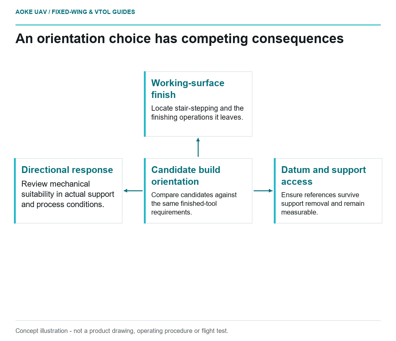
- Candidate build orientation: Compare candidates against the same finished-tool requirements.
- Working-surface finish: Locate stair-stepping and the finishing operations it leaves.
- Directional response: Review mechanical suitability in actual support and process conditions.
- Datum and support access: Ensure references survive support removal and remain measurable.