Concept illustration
Read diagram notes
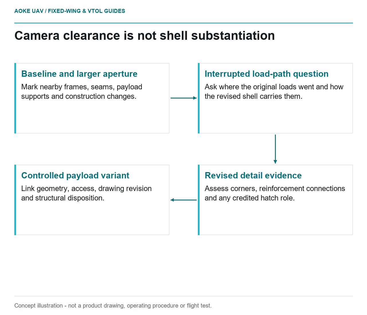
- Baseline and larger aperture: Mark nearby frames, seams, payload supports and construction changes.
- Interrupted load-path question: Ask where the original loads went and how the revised shell carries them.
- Revised detail evidence: Assess corners, reinforcement connections and any credited hatch role.
- Controlled payload variant: Link geometry, access, drawing revision and structural disposition.
A larger camera can turn a payload installation request into a fuselage design-change question. Imagine a hypothetical large fixed-wing civil survey aircraft whose belly aperture must grow to accommodate a different imaging package. This is an original integration scenario, not an GAUTEN modification or a tested design. The useful starting point is not how neatly the opening can be cut, but which structural assumptions would cease to describe the modified shell.
Interrupted shell load paths
FAA composite guidance explicitly includes cutouts, joints, and other discontinuities in its building-block approach. It explains that representative structural details help address variability and validate analytical predictions. Consequently, a laminate material description alone does not answer a question about a new opening. The document concerns certificated aircraft and provides context here, not modification approval. [1]
For the hypothetical fuselage, ask the designer to mark the proposed aperture on the actual structural arrangement. Identify nearby frames, seams, payload supports, and changes of laminate or core. Request an explanation of the loads that were originally carried through that region and the path proposed after enlargement. Keep that explanation distinct from the optical requirement for an unobstructed camera view; satisfying the latter does not substantiate the former.
Frames and local reinforcement concepts
A frame or local reinforcement is a design concept to assess, not an automatic cure for an interrupted shell. FAA guidance calls for consideration of critical loading and failure modes and for analysis supported by suitably representative evidence. It also treats holes and joints as specific structural details that may need their own substantiation. [1]
In a proposed review, compare the old and new opening boundaries, corner treatment, reinforcement terminations, and connections into surrounding structure. Ask how the proposed detail is represented in the model and which test or prior data validates that representation. Do not prescribe a universal corner radius, ply addition, or adhesive choice. Those decisions depend on the actual construction and loads, neither of which is supplied by this article.
Hatch attachments and access
Clarify whether the hatch is only an environmental closure or is credited with a structural role. This is a recommended review distinction for the scenario, not a statement that every fixed-wing hatch carries fuselage loads. If the design credits the closure, ask what attachment and installation conditions make that credit valid. If it does not, request confirmation that the open-shell structure was assessed without relying on the hatch.
FAA guidance also emphasizes access for inspection and repair and the need for documented methods appropriate to structural details. [1] Request an access review that includes the aperture corners, adjacent bonds, attachment points, and any reinforcement hidden by the installed camera. A visually tidy closure should not make the revised detail impossible to examine through the maintenance approach proposed for the aircraft.
Change control for payload variants
Treat each payload variant as a defined configuration rather than allowing the largest opening to emerge through successive undocumented trims. FAA guidance connects structural substantiation to material, process, environmental, and damage assumptions; it also calls for records of substantiated design and process changes. Those principles support a traceable change review, not an informal field-cutting permission. [1]
For the hypothetical large fixed-wing mapping fleet, propose a change package linking aperture geometry, shell drawing revision, payload support arrangement, closure configuration, and the applicable structural assessment. Ask who owns acceptance of the modification and what installation or inspection records identify the resulting aircraft configuration. Include a comparison with the baseline so that later teams can determine whether a replacement camera installation is genuinely equivalent or introduces another structural change.
Decision boundary
The decision is not whether composite fuselages can have payload openings; it is whether this particular opening and its surrounding structure have applicable evidence. Request review before enlarging the aperture, and keep camera-clearance acceptance separate from structural acceptance. No dimensions, reinforcement schedule, hatch load capacity, or flight authorization can be inferred from this fixed-wing example.
Related reading
- Removable Payload Trays Without Hidden Structural Assumptions
- A Payload Bay Checklist for Fixed-Wing Survey Sensors