Concept illustration
Read diagram notes
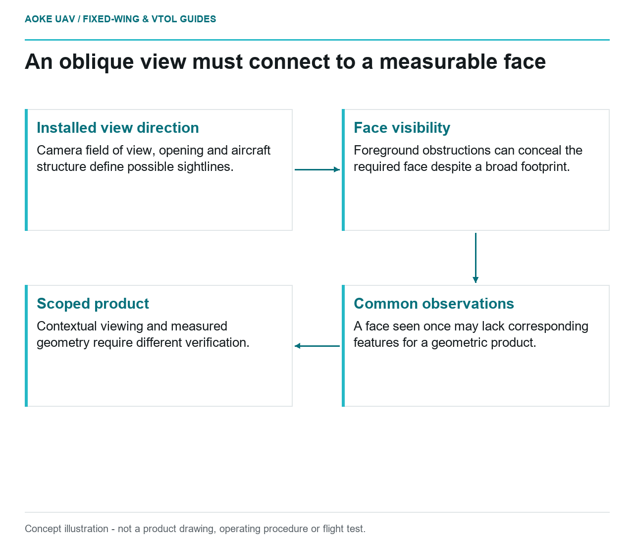
- Installed view direction: Camera field of view, opening and aircraft structure define possible sightlines.
- Face visibility: Foreground obstructions can conceal the required face despite a broad footprint.
- Common observations: A face seen once may lack corresponding features for a geometric product.
- Scoped product: Contextual viewing and measured geometry require different verification.
An oblique camera should answer a defined observation gap, not merely add another view to a payload list. Consider a hypothetical large fixed-wing mapping installation being extended to include civil infrastructure faces. The integration decision concerns which faces become observable, how the new camera is referenced and whether the resulting data can support the requested product.
View direction and footprint
USGS imagery guidance treats camera interior orientation, distortion and exterior orientation as parts of the geometric model. Position and orientation at photography time matter alongside camera parameters. That framework supports evaluating the actual viewing configuration rather than assuming that rotating an illustration defines a usable survey installation. [6]
For the hypothetical fixed-wing payload, the team would request camera-specific field-of-view information and a documented installed view direction. It would examine the relationship among the opening, camera and aircraft structure. The resulting footprint study would distinguish where an observation is geometrically possible from where its suitability has actually been demonstrated.
No generic camera tilt or flight distance is selected here. Those values would depend on the required feature, selected equipment and the aircraft’s separately established operating constraints. A wider projected area on a planning display would not itself prove more useful measurement coverage.
Occlusion and overlap requirements
USGS describes calibration and reconstruction based on common tie points across images and emphasizes their spatial distribution and stability. Merely capturing more photographs does not document which corresponding features support a particular result. [6]
The proposed oblique review would identify the intended faces and the images that show them from usable directions. It would ask whether foreground structures conceal important features and whether common observations exist for the chosen reconstruction method. A face visible in one image could have contextual value while still lacking the evidence needed for the requested geometric product.
For the large fixed-wing project, overlap would be considered in relation to the actual tilted view and terrain, not copied without review from a nadir mission. Acceptance would be defined through the required feature evidence rather than a universal percentage. This article does not establish any sensor-specific acquisition setting.
Mount geometry and navigation references
The hypothetical integration record would identify the new camera, its attachment configuration and its relationship to navigation references. The team would distinguish documented installation geometry from parameters estimated during processing. If cameras are removed or repositioned, the applicability of existing calibration evidence would be reviewed rather than presumed.
USGS recommends retaining equipment identities, settings, calibration parameters and acquisition records. Its discussion of self-calibration also shows the connection between acquisition geometry and the resulting solution. These are reasons to preserve a separate calibration identity for the proposed configuration; they are not an approved mounting procedure. [6]
Timing would have an explicit place in the review. The analyst would ask what marks the oblique exposure event and how it is related to navigation observations or other cameras. Shared project membership would not be mistaken for demonstrated synchronization.
Processing and acceptance scope
The client would define whether the oblique images are for contextual viewing, feature documentation or a measured three-dimensional product. Each proposed use would need a corresponding processing method and verification plan. An attractive textured model would not by itself establish the accuracy of a vertical-face measurement.
USGS warns against deriving accuracy guarantees from GSD alone and recommends independent quality verification. Those cautions remain relevant when the view direction changes: a nominal pixel size is not proof that the new product meets the civil requirement. [6]
The example acceptance package would therefore include observed-face coverage, original-image links, configuration and timing records, calibration evidence and independently checked outputs. Unseen or weakly supported faces would remain explicit exclusions. The defensible benefit of an oblique installation is the additional evidence it can demonstrate, not a blanket promise that it solves every limitation of nadir fixed-wing mapping.
Related reading
- Vertical Faces and the Blind Spots of Nadir Mapping
- When a New Payload Requires a Structural Reassessment