Concept illustration
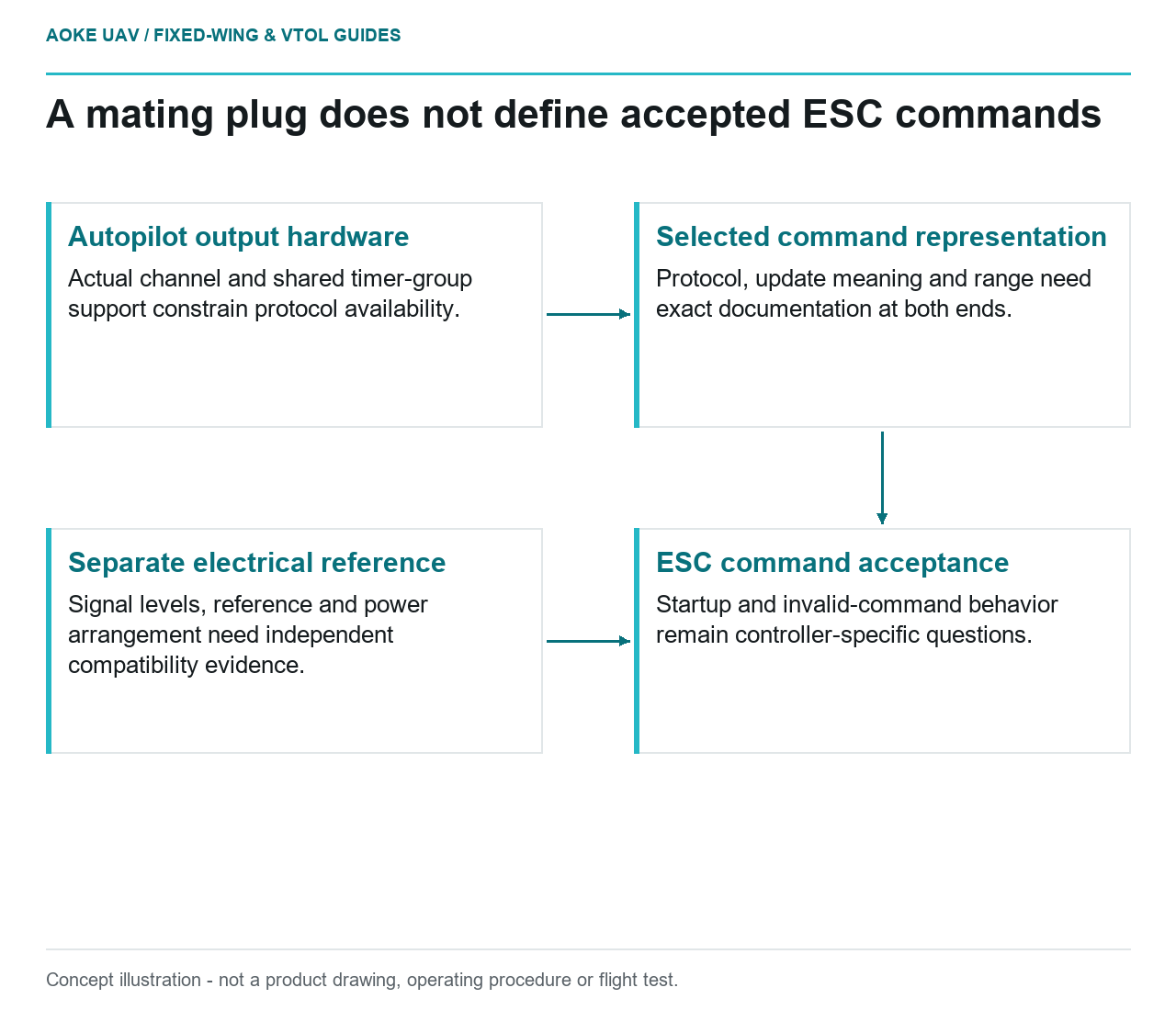
Read diagram notes
- Autopilot output hardware: Actual channel and shared timer-group support constrain protocol availability.
- Selected command representation: Protocol, update meaning and range need exact documentation at both ends.
- ESC command acceptance: Startup and invalid-command behavior remain controller-specific questions.
- Separate electrical reference: Signal levels, reference and power arrangement need independent compatibility evidence.
Define the interface at both ends
A hypothetical large fixed-wing survey aircraft is receiving a new autopilot-controller combination. The signal connector fits, but the integration packet does not identify the selected command protocol or startup behavior. Treat that as an incomplete interface definition, not a successful compatibility demonstration. This is an original civil-aircraft review scenario, not a wiring prescription.
ArduPilot documents PWM, OneShot and OneShot125 as distinct ESC command protocols and warns that the chosen configuration must be supported by the ESC. It specifically cautions that protocol changes without appropriate rebooting or calibration can produce uncommanded motor output. Those cautions belong to that documented implementation; they do not define another autopilot’s procedure. [1]
Record the autopilot hardware, firmware, selected output and exact ESC identity. Then obtain the applicable documentation for both ends. A general statement that a controller accepts throttle commands is insufficient if the project has not established which command representation the selected output actually generates.
Check signal definition and output hardware together
The ArduPilot page distinguishes pulse-width conventions and update behavior between its supported protocols. It also describes restrictions associated with output hardware, common timer groups and particular board architectures. In that system, a software selection alone is not proof that every physical output supports the requested protocol. [1]
For the illustrative large fixed-wing aircraft, ask for an output-channel map tied to the exact board documentation. If the aircraft has both forward-propulsion and VTOL motor outputs, identify each role rather than assuming a single configuration covers every channel. Preserve any restrictions that apply to shared output groups.
Electrical compatibility is a separate question from protocol naming. ArduPilot’s Pixhawk power documentation discusses signal-ground reference and distinguishes flight-controller power from servo-rail power. That is specific Pixhawk architecture context, not a universal wiring diagram. Ask the selected hardware manufacturers for the applicable interface levels, references and power arrangements instead of transplanting that example. [2]
Request the complete startup and loss-of-command story
The protocol page describes aligning autopilot output range with ESC input range and calls for rebooting after protocol-type changes in its documented workflow. This supports a request for configuration-state evidence, not permission to copy pulse widths, frame rates or calibration steps into another installation. No operational settings are prescribed here. [1]
Ask the exact controller supplier how command acceptance begins, which startup states inhibit output and how an interruption or invalid command is handled. Obtain any applicable recovery definition as well. These are open questions for the proposed aircraft’s hardware; the cited autopilot protocol page does not supply a complete selected-ESC fault specification.
For the fixed-wing VTOL scenario, keep command loss distinct from a documented controller protection event and from loss of electrical supply. They may require different evidence. A review that labels all three as failsafe without defining the triggering condition has not yet documented the propulsion interface.
Preserve configuration evidence without claiming interoperability
A proposed interface packet should retain the output map, protocol selection, relevant firmware revisions, applicable OEM documents and the approved verification record. If a team later changes a controller, board or firmware, make that change visible in the packet rather than assuming the previous evidence automatically covers the new combination.
Any bench verification needs the responsible project’s appropriate controls and exact manufacturer procedure. This explainer is not a motor-run or fault-injection instruction. Ask whether the verification demonstrates actual command acceptance and intended fault behavior; a connected cable and an exported configuration file alone do not answer both questions.
The deliverable for the hypothetical large civil fixed-wing aircraft is a defined interface with known evidence gaps. The fresh ArduPilot retrieval helps identify the kinds of protocol and output-hardware distinctions worth checking, while the Pixhawk document illustrates architecture-specific power context. Neither source proves interoperability of an unspecified autopilot and ESC or establishes aircraft-level safety.
Related reading
- ESC Protection Behavior and Aircraft-Level Consequences
- Printed Connector Assembly Aids for Payload Harnesses