Concept illustration
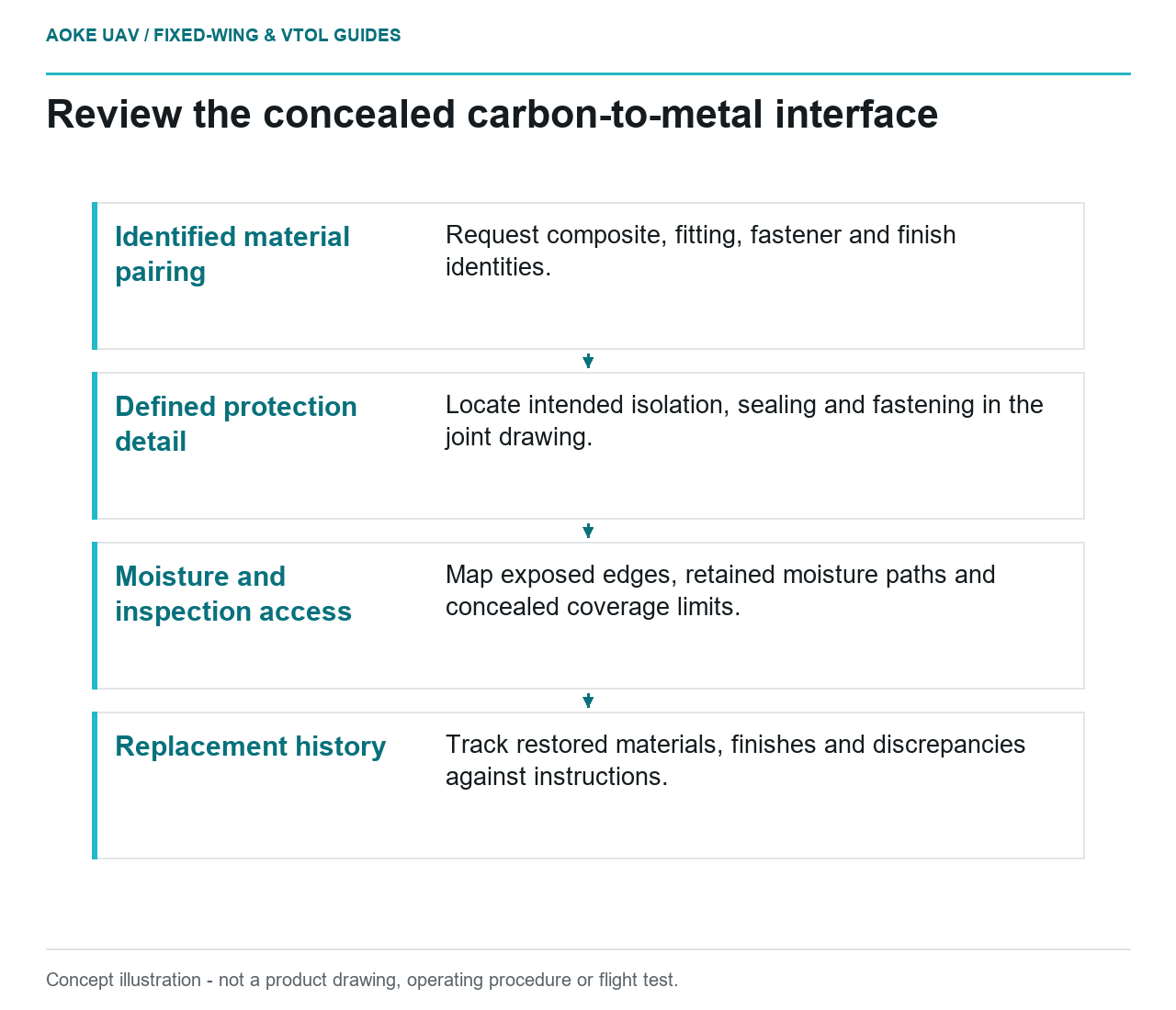
Read diagram notes
- Identified material pairing: Request composite, fitting, fastener and finish identities.
- Defined protection detail: Locate intended isolation, sealing and fastening in the joint drawing.
- Moisture and inspection access: Map exposed edges, retained moisture paths and concealed coverage limits.
- Replacement history: Track restored materials, finishes and discrepancies against instructions.
The important interface may be hidden beneath a fitting. In this hypothetical large fixed-wing civil survey aircraft, metal hardware joins carbon composite wing structure and the assembly encounters moisture during field work. The review question is what materials, protection, and inspection evidence apply at that interface. This original scenario does not identify an GAUTEN fitting, diagnose corrosion, or prescribe a universal isolation layer or fastener installation.
Dissimilar materials and moisture paths
FAA composite guidance says isolation is needed at interfaces between some composite and metal combinations to avoid corrosion. It gives carbon composite and aluminum as an example and also discusses ventilation, drainage, and protection against service degradation. Those statements concern specific material interactions, not a claim that every metal fitting on carbon is unacceptable. The guidance provides certificated-aircraft context, not approval for the hypothetical UAV. [1]
Begin the proposed fixed-wing review with actual identities: composite system, fitting material, fasteners, coatings, and any intervening layers. Request the interface drawing rather than inferring the materials from a photograph. Ask where moisture might reach or remain at the contact region under the planned service conditions. These are questions for the real design review, not a prediction that this hypothetical wing has already developed damage.
Isolation concepts and fastener interfaces
The correct isolation arrangement is a configuration-specific design matter. FAA guidance includes an example of glass plies isolating carbon from aluminum, while also requiring relevant fastener and installation procedures to address corrosion and possible composite damage. [1] An example in a circular is not enough to specify a retrofit for an unidentified fitting. Do not translate it into a universal layer count, coating selection, or tightening instruction.
For the hypothetical large fixed-wing assembly, ask which drawing defines the intended contact, isolation, sealing, and fastening arrangement. Request the evidence that the complete detail is suitable for its structural and environmental roles. If a replacement fastener or fitting has a different material or finish, identify that difference for review rather than assuming geometric interchangeability means interface equivalence. Keep the structural attachment assessment and the corrosion-protection assessment connected.
Inspection at concealed contact areas
Ask how the relevant interface can be examined using the actual maintenance instructions. A visible outer surface may not describe the condition under a fitting; this is an access question to resolve, not an invitation to dismantle a structural joint without instructions. FAA guidance calls for composite structure to accommodate inspection and repair access and for appropriate documented inspection methods. [1]
In this civil fixed-wing scenario, propose an access map identifying exposed edges, concealed contact regions, drainage features, and any protective coverings. Ask what the inspection can determine in the assembled state and what requires controlled removal or another method. If coverage is limited, record the unexamined region. Do not invent an inspection interval or describe a dry external surface as evidence that the concealed interface is free from corrosion or composite damage.
Maintenance records across replacements
Build the proposed replacement record around the configuration that must be restored. Identify the aircraft and joint, removed and installed hardware, relevant material and finish identities, applicable instructions, inspection findings, and the technical disposition of any discrepancy. These are suggested traceability fields, not a claim that a particular hardware substitution is permissible.
FAA guidance emphasizes manufacturing records for supported changes and part-specific maintenance records for repairs. Its protection discussion also treats installation procedures as part of the composite and metal interface issue. [1] For the large fixed-wing team, ask how a later maintainer will distinguish the intended isolation arrangement from an undocumented field replacement. If a coating, washer, seal, or other interface element differs from the applicable drawing, keep that discrepancy visible until the responsible organization resolves its significance.
Decision boundary
The useful outcome is an identified material pairing, documented protection detail, accessible inspection plan, and replacement history tied to the real joint. This article supplies no corrosion-rate estimate, acceptable corrosion limit, fastener torque, or isolation recipe. For the hypothetical fixed-wing wing, interface-specific design and maintenance evidence is necessary; generic confidence in carbon composite or stainless-looking hardware is not a substitute.