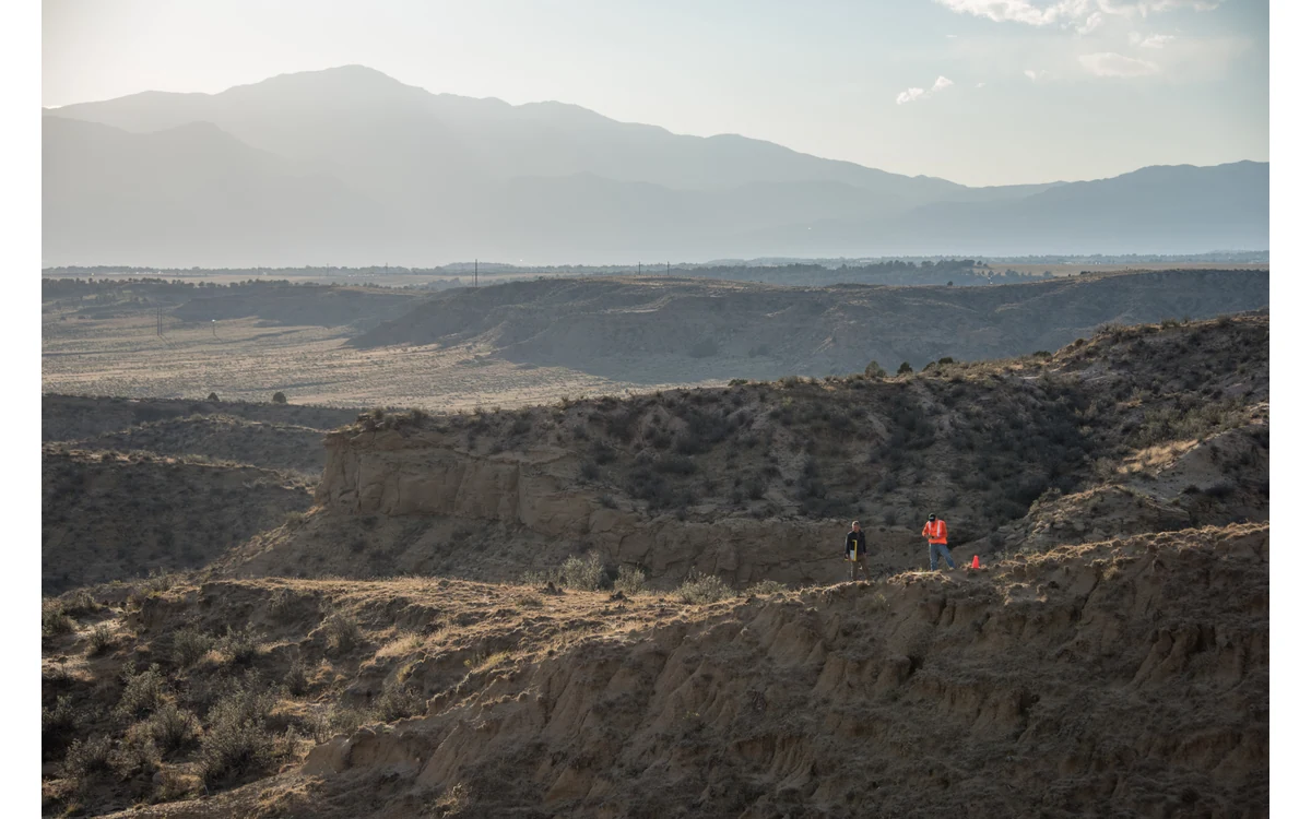
Height above terrain versus reference altitude
A hypothetical large fixed-wing UAV flies long survey lines across a civil project with both ridges and low ground. The camera plan lists one altitude, but the integration team must ask what that altitude references. For this editorial geometry example, distinguish a height relative to the mission’s reference surface from the distance between the camera and the terrain being imaged. The latter is the quantity the simplified image-footprint model needs.
Build a terrain-information register for this scenario. Record the proposed terrain dataset, its reference definition, coverage and known limitations. Ask the survey specialist how those limitations enter the image plan. Keep that exercise separate from the flight team’s assessment of terrain clearance and aircraft operation. A dataset suitable for illustrating image scale is not, by that fact alone, sufficient evidence for safe navigation or a usable flight corridor.
Changing footprint and sample distance
In a simplified downward-looking camera model with unchanged optics and orientation, changing the distance to the local surface changes the ground area represented by the image. Use that model to ask where the proposed sampling is finer or coarser, rather than reporting a single nominal value as if it applied uniformly across the whole fixed-wing block. Label the model assumptions and require the installed camera geometry to be checked before using it for project acceptance.
Do not interpret that sampling discussion as an accuracy guarantee. USGS explicitly distinguishes GSD from positional accuracy and identifies ground control, calibration and acquisition geometry as contributors to geometric quality. [1] In our hypothetical brief, retain separate requirements for spatial sampling, useful image support and independent product assessment. If a proposal supplies only one nominal GSD, ask for the terrain assumptions behind it and the evidence needed where those assumptions are weakest.
Occlusion and coverage planning
Use the terrain review to ask a second question: which surfaces will actually be visible from the proposed image positions? In this scenario, mark steep features and terrain breaks for visibility assessment rather than assuming that a broad image footprint contains an observation of every surface within it. An outline on a plan is not the same thing as accepted image support for the intended measurement. Do not invent a complete surface simply to make the footprint look continuous.
For the large industrial fixed-wing installation, refer coverage conflicts back to both survey and aircraft integration teams. Ask whether revised strip geometry or a qualified measurement area could address them within documented constraints. Do not prescribe abrupt terrain-following manoeuvres or an arbitrary lower altitude to improve detail. If the proposed aircraft is fixed-wing VTOL, the vertical-launch capability does not settle the feasibility of the long survey segment being examined.
Inspect terrain-dependent output quality
USGS notes that vertical accuracy depends on terrain and geometry, and discusses distributing tie points horizontally and vertically, potentially adapting processing boundaries to terrain. [1] That supports a spatially explicit review rather than a single block-wide assurance. In our hypothetical workflow, compare image support and output assessment across different relief zones, with independent reference observations where the project requires them. No actual residuals or terrain measurements are available in this example.
At delivery, retain a clear distinction between planned sampling and assessed output quality. Document where local scale was expected to vary, where image support was insufficient and what those limitations mean for the requested civil measurements. Tie exceptions to identifiable regions and source images so a reviewer can investigate them. The objective is an honest terrain-dependent account of a large fixed-wing survey, not a promise that one reference altitude produces uniform resolution, complete visibility or verified terrain clearance.
For an illustrative relief-zone record, separate the terrain dataset’s stated height reference, the mission altitude reference and the camera-to-surface distance assumed by the image model. Add the region where that assumption is being evaluated and the output sampling requirement. An unresolved reference mismatch should remain open even if the planner draws plausible-looking footprints. This gives the fixed-wing survey team a specific information problem to resolve without implying that the image model has assessed aircraft clearance.
Related reading
- Coordinate Reference Systems at UAV Survey Handover
- Wind Profiles and Fixed-Wing Inspection Planning
Sources
Visual summary
Concept illustration
Read diagram notes
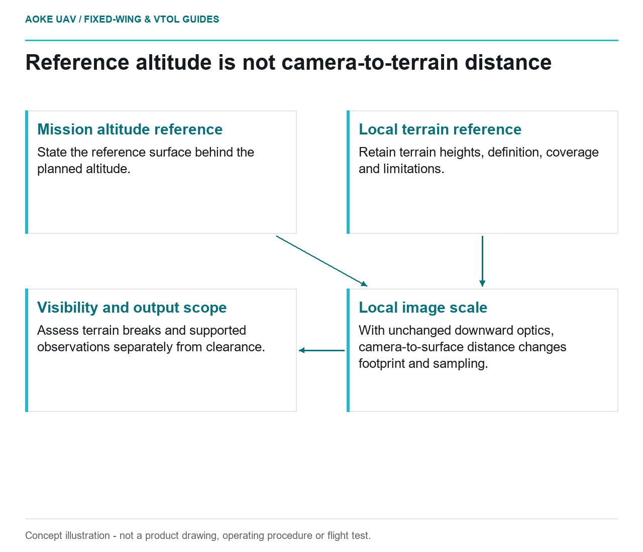
- Mission altitude reference: State the reference surface behind the planned altitude.
- Local terrain reference: Retain terrain heights, definition, coverage and limitations.
- Local image scale: With unchanged downward optics, camera-to-surface distance changes footprint and sampling.
- Visibility and output scope: Assess terrain breaks and supported observations separately from clearance.